Model IFP-2100/ECS Installation Manual LS10143-001SK-E
4-21
4. Place the trim ring over the backbox as shown in Figure 4-29.
Figure 4-29 Installing Trim Ring
5. Connect wires from the RA-100 to the SBUS connectors on the FACP. (See Figure 4-30).
6. Attach the annunciator and door assembly to the backbox using screws provided.
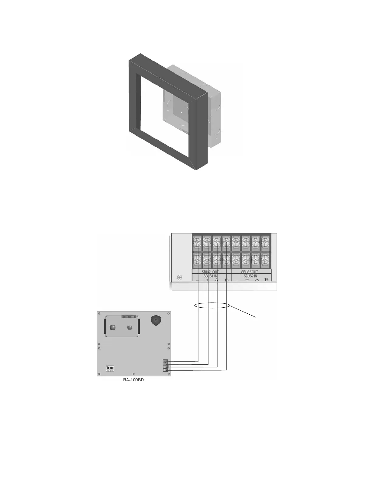
4.7.2 Model RA-100 Connection to the Panel
Connect the RA-100 to the panel as shown in Figure 4-30.
Figure 4-30 Model RA-100 Connection to the Panel

 Loading...


