LS10143-001SK-E Control Panel Installation
4-36
2. Configure the circuit through programming (see Section 9.5).
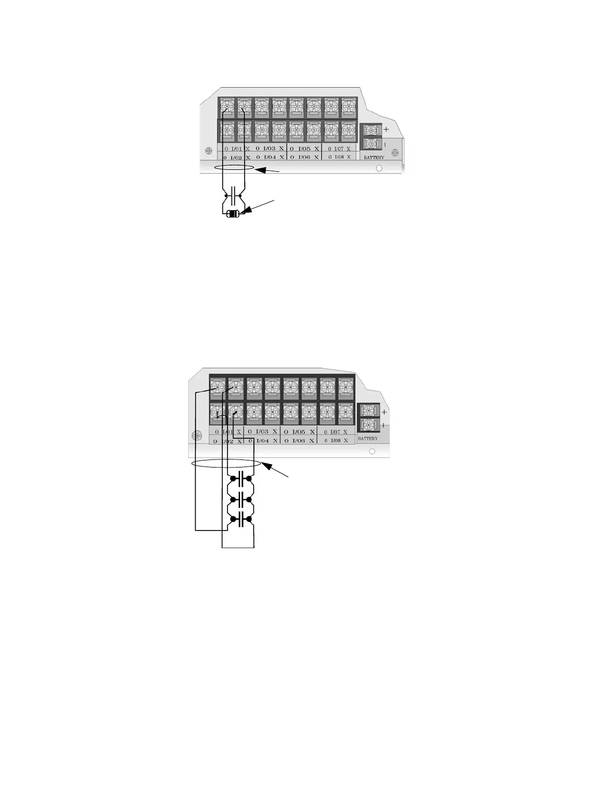
Figure 4-49 Class B Input Switches
4.15.2.2 Class A Inputs
You can connect conventional Class A switches, such as waterflow switches and pull stations, directly to the
Flexput circuits of the control panel.
To install a Class A switch:
1. Wire the Class A switch as shown in Figure 4-50.
2. Configure the circuit through programming (see Section 9.5).
Figure 4-50 Class A initiating Switches
Note: In programming any point that uses multiple Flexput circuits, the lowest Flexput circuit number is used to
refer to the circuit pair. For example, Figure 4-50 uses both Flexput circuit 1 and 2, so in programming it
would be referred to as point 1.
4.15.3 Installing 2-Wire Smoke Detectors
Any compatible UL listed two-wire smoke detector can be used with the control panel (see Appendix A for list
of compatible smoke detectors). Figure 4-51 and Figure 4-52 illustrate how to connect a UL listed 2-wire
detector to the control panel.
supervised
Maximum Impedance
per circuit is 50
Ω
power limited
EOL 4.7 kΩ
Note:
Flexput circuit 1 and 2
used as an example.
Any Flexput point pairing
could be used.
supervised
power limited
Maximum Impedance per circuit is 50Ω

 Loading...


