Model IFP-2100/ECS Installation Manual LS10143-001SK-E
4-25
4.10 5824 Serial/Parallel Interface Module Installation
The 5824 serial/parallel interface module allows you to connect a printer to the panel, so you can print a real-time
log of system events. Instructions for installing the 5824 appear below. The 5824 is for ancillary use only.
5824 installation involves the following steps:
1. Ensure that all power has been removed from the FACP.
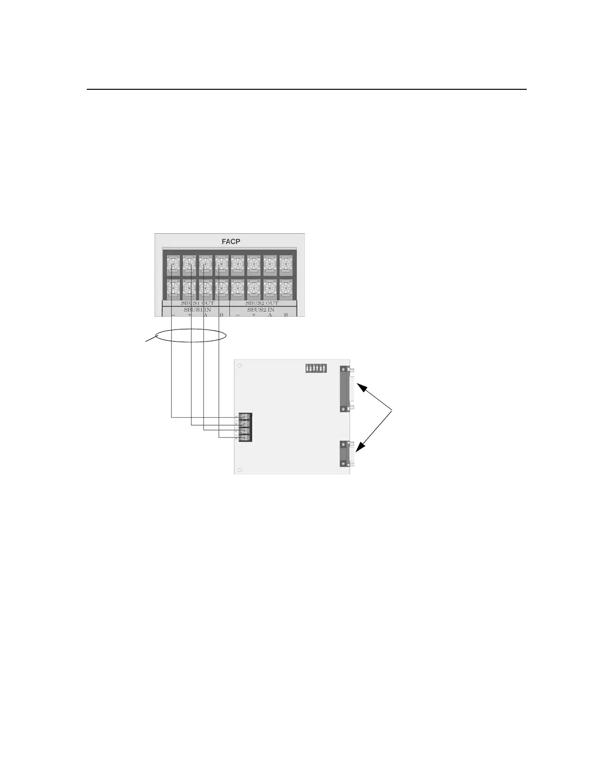
2. Connect the 5824 to the FACP as shown in Figure 4-35.
Note: Four 5824s per panel maximum.
3. Use the DIP switches on the 5824 board to assign an SBUS ID# to the 5824 (see Section 4.13.1).
4. Configure the 5824 device through programming. See Section 4.10.1.
Figure 4-35 5824 Connection to the Panel
4.10.1 Selecting 5824 Options
Configuring the 5824 includes the following steps:
• Add the module to the system. JumpStart will add the module automatically (see Section 8.1). You can also
add it manually (see Section 9.2.2).
• Select a name, if desired (see Section 9.2.1.2).
• Select options for the printer and the output port.
Printer and Output Port Options
1. From the Main Menu, select 7 for Panel Programming.
2. Select 1 for Module.
3. Select 1 for Edit Module.
Supervised
Power Limited
Model 5824 Board
Parallel
Serial
Cable
Connectors
for Connection
to Printer

 Loading...


