EasyManua.ls Logo

Honeywell EXCEL 5000 User Manual

Honeywell EXCEL 5000
282 pages
To Next Page IconTo Next Page
To Previous Page IconTo Previous Page
Page #224 background imageLoading...
Page #224 background image
ALPHABETIC REFERENCE EXCEL CARE CONTROL ICONS
74-5577–33 (US) 226
EN2B-0184 GE51 R0518 (Europe)
Other Examples See the Examples chapter for other applications that use the DIF icon.
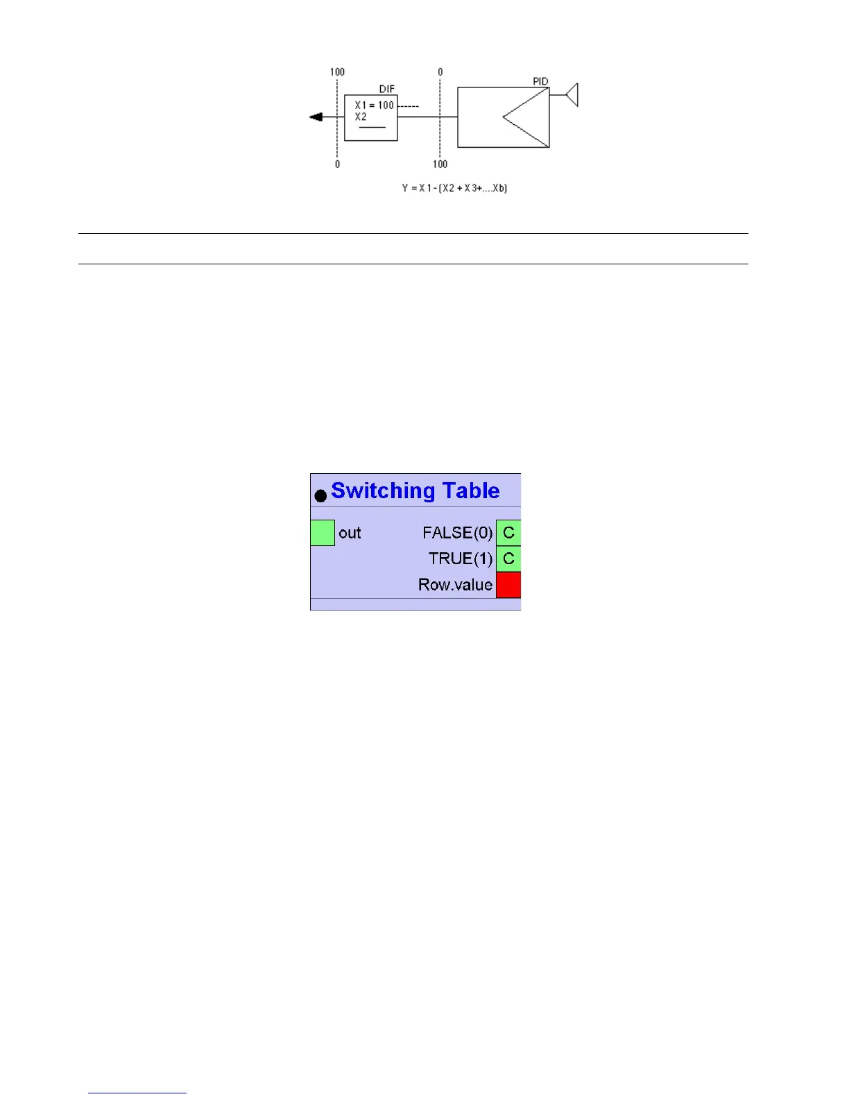
Switching Table (Excel Web / Excel Web II)
Function The Switching logic module sets the value of the TRUE(1) or FALSE(0) input to the
output depending on the defined logic.
Switch Cases can be defined for the HVAC system (e.g. Fire or Frost). In the
Switching Logic / Rows section, logic operations have to be created that are relevant
for the Switch Cases.
A logic operation is the comparison of an Actual Value with a Comparison Value
using the defined condition.
For the Switch cases, it can be determined which logic operation is relevant. If all
these logic operations are TRUE (AND relation), the Switching Table becomes
TRUE and the TRUE(1) input value is set as output value of the Switching Table.
If none of the Switch Cases results to TRUE (OR relation), the FALSE(0) input value
is set as output value.
I/O Dialog Box
Input Two fixed inputs, containing the FALSE(0) and TRUE(1) values.
Two through thirty two input blocks, each representing one row, where:
<Input Name>.Actual Value = value
<Input Name>.Comparison Value = comparison value (invisible by default)
<Input Name>.Hysteresis = switching hysteresis (invisible by default)
Output One output (out). The output is set to one of the inputs FALSE(0) or TRUE(1)
depending on the result of the switching logic (TRUE or FALSE).
A Switching Table contains the Output Value Definition section, the Switch Cases section and the Switching
Logic section.
Output Value Definition Definition of the output:
TRUE Value = setup of input TRUE(1) (connection, Datapoint Property etc.)
FALSE Value = setup of input FALSE(0) (connection, Datapoint Property etc.)
Output = setup of output (connection, Datapoint Property etc.)
Output Delay = time delay of the output validity
Switch Cases/Columns Definition of Switch Cases for an HVAC system (e.g. Fire, Frost):
Switch Case = name of the case
Delay = time delay of the Switch Case validity
The Switch Cases have an OR relation to each other !

Table of Contents

Other manuals for Honeywell EXCEL 5000

Question and Answer IconNeed help?

Do you have a question about the Honeywell EXCEL 5000 and is the answer not in the manual?

Honeywell EXCEL 5000 Specifications

General IconGeneral
BrandHoneywell
ModelEXCEL 5000
CategoryControl Systems
LanguageEnglish

Summary

Introduction to Control Icons

Control Icon Operation

Explains how control icons function, including internal parameters and I/O dialog boxes.

Control Icon Table

Provides a list of control icons with their names, symbols, and brief descriptions.

Alphabetic Reference of Control Icons

Absolute (Excel Web / Excel Web II) Icon

Describes the Absolute control icon, its function, and I/O.

Addition / ADD Icon

Details the Addition/ADD control icon for summing input values.

ADH2 (Excel Web / Excel Web II) Icon

Explains the ADH2 control icon for legacy RACL heating curve slope calculation.

Analog Switch / SWI Icon

Describes the Analog Switch/SWI icon for switching analog values based on digital input.

AND (Excel Web / Excel Web II) Icon

Details the AND control icon for logical AND operations.

Arcus Cosinus Icon

Describes the Arcus Cosinus control icon for calculating arcus cosinus function.

Arcus Sinus Icon

Describes the Arcus Sinus control icon for calculating arcus sinus function.

Arcus Tangens Icon

Describes the Arcus Tangens control icon for calculating arcus tangens function.

Average / AVR Icon

Explains the Average/AVR control icon for calculating average of analog inputs.

Cascade / CAS Icon

Describes the Cascade/CAS control icon for master and secondary PI control.

Cascade Plus / CAS Icon

Details the Cascade Plus/CAS icon with integral action enable/disable input.

Changeover Switch / CHA Icon

Describes the Changeover Switch/CHA icon for passing analog values based on digital input.

Compare 2 Icon

Explains the Compare 2 icon for comparing two analog inputs.

Comparison Icon

Describes the Comparison icon for comparing two analog inputs.

Cosinus Icon

Describes the Cosinus icon for calculating the cosinus function of X.

Counter Icon

Describes the Counter icon for incrementing output based on input changes.

Cycle / CYC Icon

Explains the Cycle/CYC icon for outputting a digital value on a cyclic basis.

Fixed Applications (XFM)

Introduces Extended Function Modules (XFMs) for additional control strategy functionality.

ENHANCED PID Icon

Describes the ENHANCED PID icon with advanced PID features.

Power Demand Control XFMs

Details Power Demand Control XFMs for energy consumption management.

XFM 35 Description

Provides a description of the XFM 35 strategy program for load optimization.

XFM 35 General Functions

Lists general functions provided by the XFM 35 for load optimization.

XFM 35 Algorithms

Details the Sliding Window, Ideal Curve, and Extrapolation algorithms used by XFM 35.

XFM 36-1 Description

Provides a description of XFM 36-1, 36-1S, and 36-1R single-stage load programs.

XFM 36-1/S Sequential Load Switching

Details sequential load switching based on rank within priority groups.

XFM 36-1/R Rotational Load Switching

Describes rotational load switching based on ON/OFF duration for XFM 36-1/R.

Heating Curve with Adaptation / HCA Icon

Explains the HCA icon for adaptable heating compensation curve calculations.

Mathematical Editor / MAT

Describes the Mathematical Editor for creating formulas to modify control icon inputs.

Optimum Start/Stop / EOH Icon

Describes the EOH icon for optimizing heating plant start/stop and supply water setpoint.

Heating Optimization WITHOUT Room Sensor

Explains heating optimization using outdoor air temperature, without a room sensor.

Cool-Down Optimization WITH Room Sensor

Describes cool-down optimization considering room temperature and sensors.

Optimum Start/Stop / EOH3 Icon

Describes the EOH3 icon for optimizing heating plant and supply water setpoints.

Cool-Down Optimization WITHOUT Room Sensor

Explains cool-down optimization based on outdoor air temperature.

Optimum Start/Stop Energy Optimized Ventilation / EOV Icon

Describes the EOV icon for optimizing start/stop of air conditioning systems.

PID Controller / PID Icon

Describes the PID Controller/PID icon for analog output regulation.

PID Plus Controller / PID Icon

Describes the PID Plus Controller/PID icon with an additional digital input.

ZEB Icon

Describes the ZEB icon for determining setpoints for comfort bands.

Examples of Control Applications

Floating Limits and Alarm Suppression

Discusses adapting sensor limits and suppressing nuisance alarms.

Operating Pump Switchover

Switches pump operation between two pumps based on operating hours.

Optimized Start/Stop

Optimizes start/stop times for air conditioning systems to save energy.

Positioning Signal Limitation

Limits the range of output values sent to a positioning signal.

Setpoint Adjustments

Adjusts setpoints for Time Programs based on operating modes.

System Regulation

Regulates partial air conditioning systems using ZEB and PID controllers.

Related product manuals