EXCEL CARE CONTROL ICONS EXAMPLES
249 74-5577–33 (US)
EN2B-0184 GE51 R0518 (Europe)
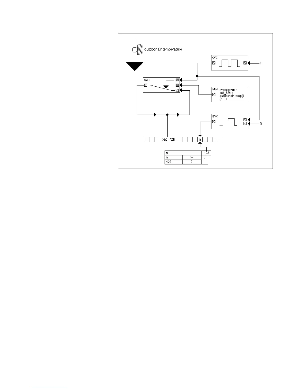
Control Sequence The following diagram illustrates the control sequence in CARE.
The CYC statement generates a series of impulses with a period duration of 10
minutes (scan time). To do this, the CYC icon must have the following parameter
assignments:
Switch-on time = 599 sec
Switch-off time=1 sec
NOTE: To guarantee correct operation, switch-on time must equal cycle time. This
rule is the only way to ensure that the impulse is present during an entire
cycle and is interpretable.
With a cycle time of 5 seconds, switch-on time must be 1 second and switch-off time
599 seconds.
Impulses from CYC are input to EVC and stored temporarily in a flag (n).
The MAT icon contains the averaging formula:
Average = (n * oat_72h + OAT)/(n + 1)
Where:
Average is the actual average value calculated.
oat_72h is the OAT average over 3 days.
OAT is the momentary OAT from the OAT sensor.
n is the weighting factor.
This new average value replaces the old OAT average over 3 days as soon as the
output of the CYC statement delivers a high signal. During the switch-off duration of
CYC, average OAT is in a self-hold circuit. The SWI icon implements this function.
The switching table implements the maximum limitation of the weighting factor (n =
422). The table resets n to 422 if it exceeds 422.
In addition, the CYC input must be set to logical 1 so the impulse generator is
released. The output XD2 of EVC is set to logical 0. If this input becomes 1, a reset

 Loading...


