EXAMPLES CARE CONTROL ICONS
74-5577–33 (US) 272
EN2B-0184 GE51 R0518 (Europe)
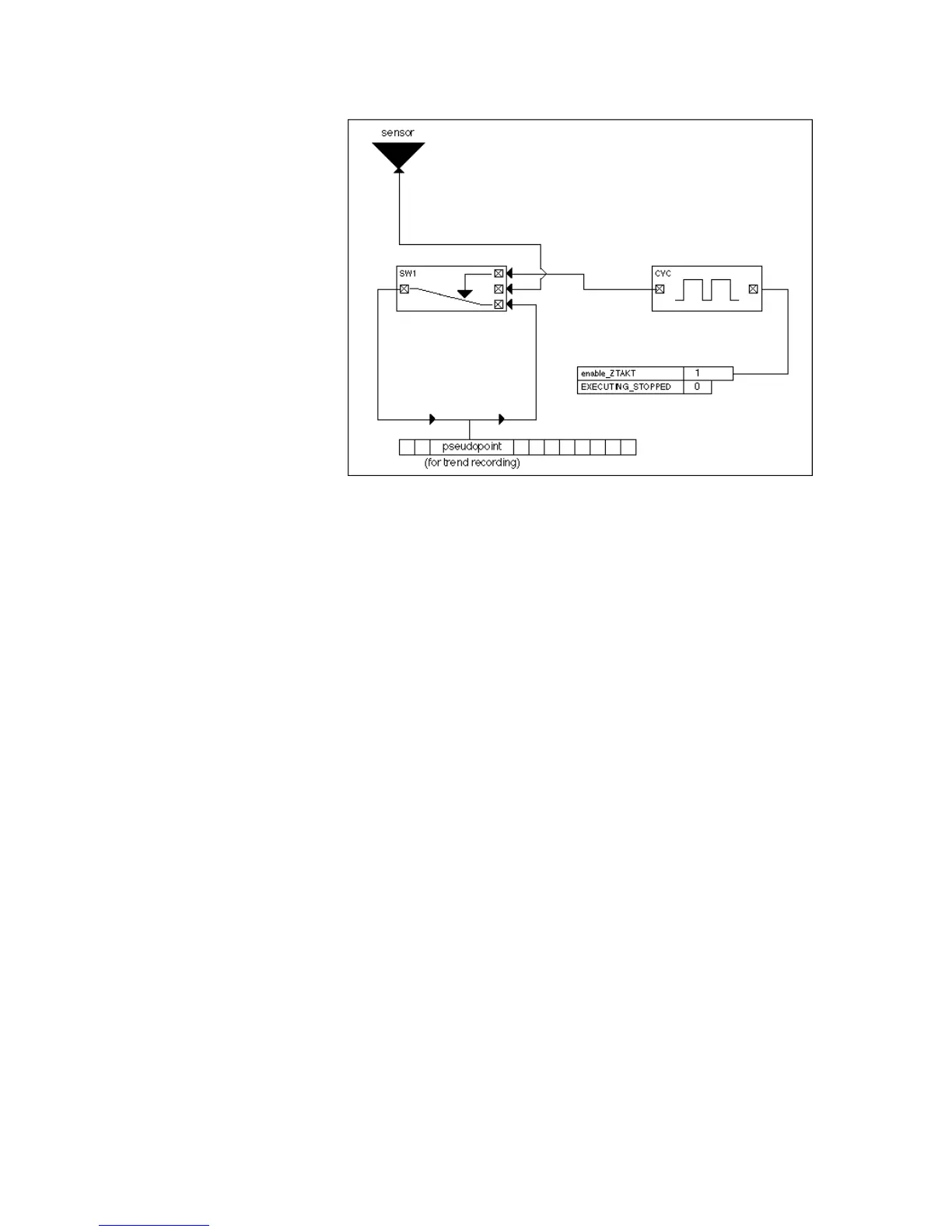
To implement this extended trend function, CYC must be part of a control loop that
includes other functions. The following diagram illustrates the complete control loop.
The SWI control icon switches the value of the sensor to the pseudopoint when CYC
is in On time. Otherwise, SWI implements a self-hold time for the sensor.
The switching table uses the system variable EXECUTING_STOPPED. The
controller automatically sets this variable to LOW as soon as a DDC program has
run correctly. If the program is done, the controller sets the variable to HIGH. The
switching table for the release of the time cycle is therefore true exactly when a
program is running.

 Loading...


