Fire Alarm Control Panel IQ8Control C/M
50 FB 798951.GB0 / 01.09
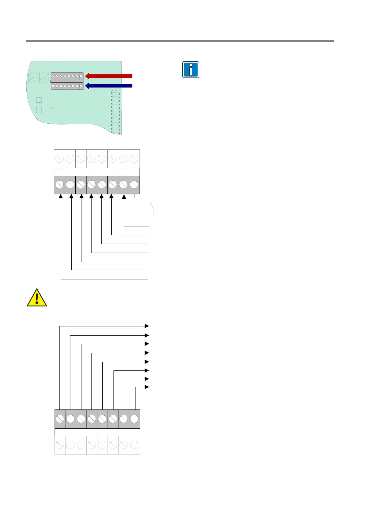
4.3.7 Connecting a fire department operating panel
Wiring differs from area to area and is
governed by the requirements of the
regional fire department.
A 12 V DC voltage is required for
operation.
X4
bottom - terminals
top - terminals
IN1
IN8
IN2
IN3
IN4
IN5
IN6
IN7
X4
FD call LED on
(IN1 on GND)
(closer)
MB disconnected
acoustic signals off
check MB
reset FACP
fire control off / revision
do not use
top
terminals
do not use
If the terminal IN8 (fire control off / revision) is not used, jumper BR21 must always be fitted at
position 2-3 !
Current load per output (OUT1 to OUT 8) max. 25 mA.
OUT1
OUT8
OUT2
OUT3
OUT4
OUT5
OUT6
OUT7
X4
MB activated
extinguishing system activated
common fire
MB disconnected
MB activation prevent
do not use
acoustic signals off
fire control off (revision)
bottom
terminals
Fig. 44: Connection terminals fire department operating panel

 Loading...


