169
oratanypointalongthe20mAloop�Additionally,theoptionallocal
HARTinterface(P/N:XNX-HIF)permitstemporaryconnectionofa
HARTterminaltothetransmitter�ThislocalHARTportistransformer-
coupledtothemain20mAoutput�Thisportisintrinsicallysafeand
polarityinsensitive�SeeSection2�3�1formoreinformation�
TheinternalHARTmodemfunctionsasahigh-impedancecurrent
source�ThustransferringtheHARTsignalrequiresacertainminimum
loopresistancebetweentheslaveandalow-impedancepower
supply�
Normally,thisresistanceissuppliedbythecontrolsystemandso
neednotbeexplicitlyadded�However,specialtreatmentisneeded
whenthe20mAoutputisnotusedandthelocalHARTinterfaceis
needed�(Aninstallermightchoosetocommunicateusingrelays,
Modbus
®
,orFoundation
TM
Fieldbusinstead�)Inthiscase,the
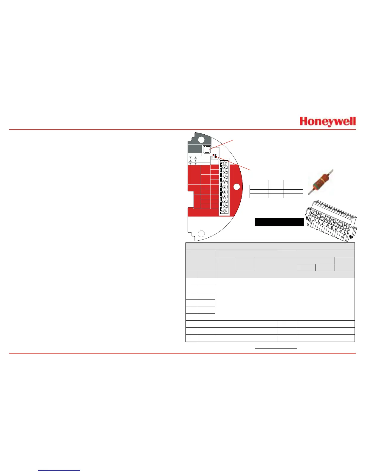
supplied510ohmresistormustbettedtocreatean“articial”20
mAloop�TheresistorshouldbeconnectedbetweenTB-1terminal
1-3andterminal1-6�Additionally,S1andS2shouldbeplacedin
“source”conguration�ThisisshownschematicallyinFigure237�
ThedigitalHARTinterfaceprovidesallofthecapabilitiesofthelocal
userinterface�TheXNXtransmitterhasbeendesignedtousethe
portableEmersoneldcommunicatorwithDevCom2000softwarefor
MicrosoftWindows
®
andEmersonAMSIntelligentDeviceManager�
UsingHART,aservicepersoncandisplayinformation,test,calibrate,
andcongure�AmapoftheHARTmenusisprovidedinSection
A�1�3�
ATEX Conditions for Safe Use of Intrinsically Safe
HART Handheld Devices
ForinstallationsinwhichboththeCiandlioftheintrinsicallysafe
apparatusexceeds1%oftheCoandloparametersoftheassociated
apparatus(excludingthecable),50%ofCoandloparametersare
applicableandshallnotbeexceeded,i�e�,theCiofthedeviceplus
theCofthecablemustbelessthanorequalto50%oftheCoof
theassociatedapparatus,andtheliofthedeviceplusthelofthe
cablemustbelessthanorequalto50%ofthelooftheassociated
apparatus�
Figure 235. XNX mV Personality
Board Terminal Blocks, Jumper Switches
and Wire Color Chart
HART
20 mA
Operation
LOCAL
J1
S1
+V 1-1
mV TB-1
MPD, 705
Sensepoint
4-20mA
HART
16-32 VDC
6.5W max.
1-2
-V 1-3
1-4
+mA 1-5
-mA 1-6
Sense
1-7
0v 1-8
Ref 1-9
S1
Source
Sink
Isolated
S2
S2
XNX mV TB-1
▼▼
S2S1
▼▼
Isolated
▲
Sink
▼
Source
J1 - Local HART Option Connector
S1 and S2 - 20mA Output
Jumper Switch
▼
▲
mVSensorType
CatalyticBead MPDw/IR
MPD
705
705HT
S’point
S’pointHT
S’point
PPM
IR5%
IRFlam
CO
2
CH
4
TB-1 Desc. WireColorfromSensor
1 24v
SeeSection2.2.4.
2
3 Gnd
4
5 20mA+
6 20mA-
7 Sense Brown Red Brown
8 0v White Green White
9 Ref Blue Blue Blue
InternalGround
1
2
3
4
5
6
7
8
9
510OhmResistor

 Loading...


