71
Searchline(seethetableinthenextcolumn)�
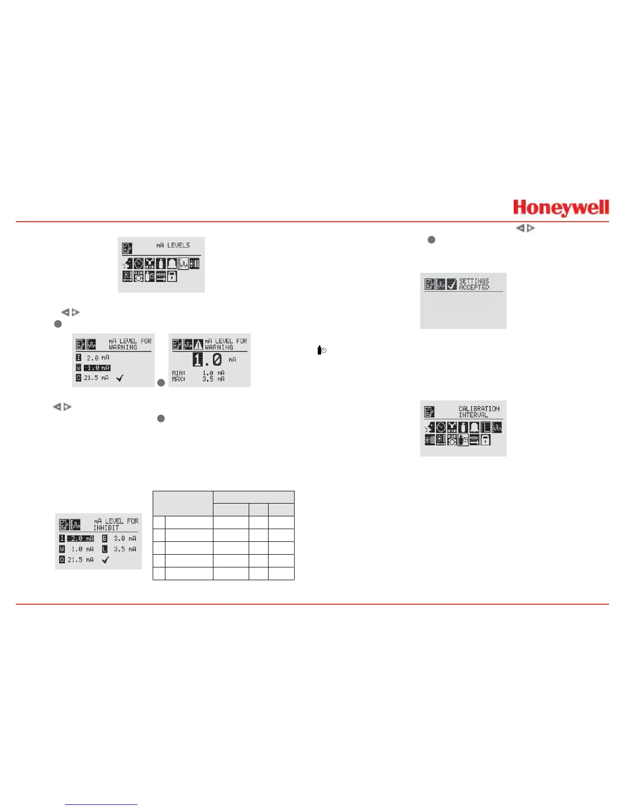
Figure 102. mA Levels Menu
Usingthe switches,movetothemAoutputtobechanged
anduse
✓
toselectit�
✓
Figure 103. Set mA Levels for Warning
Usethe switchestodecrementorincrementthevalueuntil
thedesiredvalueappears�Use
✓
toselectthevalueandmove
tothenextsetting�Repeatforeachsettingtobechanged�
ThedefaultvaluesandavailableoutputrangesforInhibit,
Warning,Overrange,BeamBlocked,andLowSignalareshown
inthefollowingtable�SeeSection5Warnings/Faultsformore
information�
Signal
Output (mA)
Default Min Max
I
Inhibit 2.0 1.0 3.5
W
Warning 3.0 1.0 3.5
O
Overrange 21.0 20 22
B
BeamBlocked 1.0 1.0 4.0
L
LowSignal 1.0 1.0 4.0
Figure 104. Set mA Levels for Inhibit
Afterallchangeshavebeenmade,usethe switchesto
movetothe‘ü’anduse
✓
onthefrontpaneltoacceptandsave
thesettings�If ‘ü’isnotselected,noneofthechangeswillbe
saved�
Figure 105. mA Settings Saved
Calibration Interval
CalibrationIntervalallowsadesiredintervalforsensor
calibrationtobesetforsensorsattachedtothetransmitter�The
transmitterwillgenerateawarningwhentheintervalisreached�
Figure 106. Calibration Interval Menu
CalibrationIntervalwillnotappearwhenanIRpersonalityboard
isattachedandthemAsensortypeissetas‘OthermASensor’�
Thedefaultcalibrationvaluesforthe“CalibrationRequired”
diagnosticvarybasedonsensortype�Thisvaluecanberepro-
grammedinaccordancewithsiterequirementstoensurethe
highestlevelofsafety�Correctoperationofeachsensorshould
beconrmedusingcalibrationwithacertiedgasofknowncon-
centrationbeforecommissioning�
AlthoughthecalibrationIntervalcanbesettoanyvaluebe-
tween0and360days,HoneywellAnalyticsrecommendsthatthe
intervalforelectrochemicalandcatalyticsensorsbesetto180

 Loading...


