47
theXNXTransmitterandOptimaPlusorExcelis100feet(33
meters)using0�75mm
2
(18AWG)wireminimum�
Note: Asecond,black-handledscrewdriverisincludedforuseon
terminalblocks2and4.Thistoolissmallerthanthemagneticwand
andisdesignedtofitintotheterminalconnectionsonTB2andTB4.
TheSearchpointOptimaPlusorSearchlineExcelcanbe
suppliedineitherSinkorSourcemodeoperationandistypically
labeledonthewhitewireexitingtheSearchpointOptimaPlusor
SearchlineExcel�UsethetableinFigure50tosetS3andS4to
thesameoutputtypethatappearsonthewiretagoftheIR
device�
FormoreinformationseetheSearchpointOptimaPlusOperating
Instructions(2104M0508)ortheSearchlineExcelTechnical
Manual(2104M0506)�
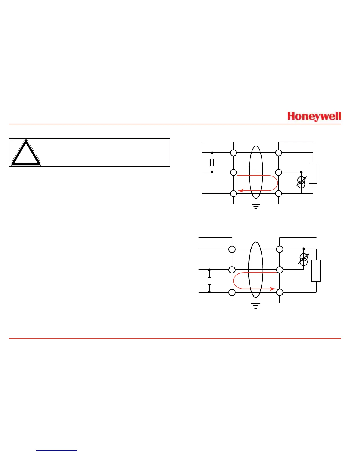
Connecting Generic mA Devices
UsethefollowingschematicstosetswitchesS3andS4They
must
besettothesameoutputtype(whichappearsonthewire
tagofthemAdevice)�
TheIRpersonalitytypeprovidesforagenericmAinputunder
sensortypeconguration�Thetransmittercanbeusedto
convertthemAinputtobereadoverHARToroptionalModbus
orFoundationFieldbusprotocolsandsetoptionalrelays(if
equipped)�AdditionalcongurationofgastypeandunitID
forreportingisrequired(seeGasSelection)�ForGenericmA
devices,inputvaluesbelow3mAwillgenerateFault155�
XNX
+IR
Signal
-IR
R
L
1-7
1-9
1-8
+V
+mA
-V
mA Device
Current
Flow
24V 7W Max
XNX S3 and S4 must be in the UP position
Set mA Device and XNX to the same output type.
Figure 49. XNX mA input sink conguration
XNX
+IR
Signal
-IR
R
L
1-7
1-9
1-8
+V
-mA
-V
mA Device
Current
Flow
XNX S3 and S4 must be in the DOWN position
Set mA Device and XNX to the same output type.
Figure 50. XNX mA input source conguration

 Loading...


