37
2.2.4
4-20mA Output, Common Connections, and
Power Settings
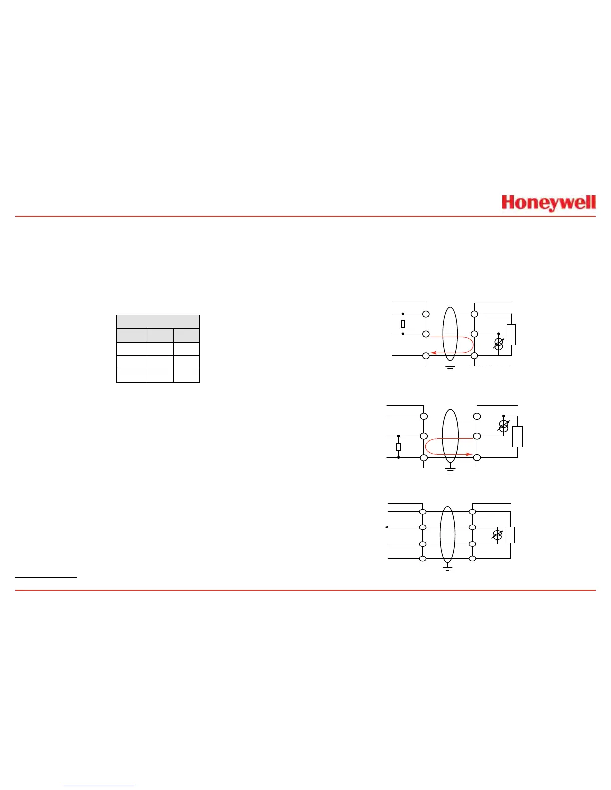
TheXNXUniversalTransmitterallowstheusertocongure
the4-20mAoutputtoSink,Source,orIsolatedmode
operationviatwoprogrammingswitchesonthePOD
1
�The
SwitchCongurationtableshowstheS1andS2settingand
correspondingoutputconguration�
Switch Conguration
Mode S1 S2
Source Down Up
Sink Up Down
Isolated Down Down
Mostcontrollersinthemarketwillacceptsource-congured
devices�Sink-conguredsignalsareusedinoldertechnology
controllers,whichreducetheneedforcompletesystem
upgrades�Inisolated-signaldevices,ifthecontrollerfailsorthe
mAsignalwiresaredisconnectedorbroken,theelddevicewill
remainoperational�Mostcontrollersinthemarketwillaccept
isolatedcongureddevices�
Powerand4-20mAconnectionsaremadeatTB-1andare
identicalfortheEC,IR,andmVPersonalityBoards�Foruser
convenience,asecondsetof+Veand-Vepowerterminalshave
beenprovidedtoeliminatetheneedforasecondaryjunction
boxinmulti-nodesystemswhenusedwiththesuppliedterminal
jumpers�
Thetotalloadresistanceforthe4-20mAoutputshouldbe
keptlowerthan500Ω,includingtheresistanceoftheproperly
selected4-20mAcableandinputimpedanceoftheequipment
tobeconnnected�Theminimumloopimpedenceis200ohms;
1 The 4-20 mA output state is refreshed at least every two seconds (once per second is typical).
themaximumis500ohms�Ifthe20mAoutputisnotused,a500
ohmresistormustbeinstalled�
TheXNXUniversalTransmitterpowerconsumptionisdependent
onthesensorandoptionsforthespecicconguration�For
properoperation,theinputvoltagemustbemaintainedat16to
32VDCforECandmVunitsand18to32VDCforIRunits�

 Loading...


