55
2.4 Powering the XNX for the First Time
2.4.1XNXUnitsConguredforEC,mV,andIR
(except Searchline Excel)
Aftermounting,wiringthetransmitter,wiringthespecicmVorIR
sensororinstallingtheECcartridge,theinstallationisvisuallyand
electricallytestedasdescribedbelow�
Warning: Minimumandmaximumcontrolleralarmlevelsshouldnot
besetatlessthan10%orgreaterthan90%ofthefullscalerange
ofthesensor.CSAandFMagencylimitsare60%LELor0.6mg/m
3
.
1�Verifythatthetransmitteriswiredcorrectlyaccordingto
thismanualandtheassociatedcontrolequipmentmanual�
2�Ifequipped,unscrewtheweatherproofcover,loosenthe
sensorretainerlockingscrew,andunscrewtheretainer�
3�ForECsensors,pluginthesensorcartridge,takingcareto
alignthesensorpinswiththeconnectorholesinthePCB�
Caution: Fortoxicsensors,removetheshortingclipfromthebottom
ofthesensorpriortoinstallation.NoshortingclipisprovidedwithO
2
sensors.
4�Retthesensorretainer,tightenthelockingscrewandret
theweatherproofcover�
Note: Beforereplacingthecoveronthetransmitterhousing,coatthe
threadswithanti-seizecompoundtopreventcorrosionbuildup.
Note: InspectthecoverO-ringforcrackingoranyotherdefectsthat
mightcompromisetheintegrityoftheseal.Ifitisdamaged,replace
withtheO-ringsuppliedintheaccessorykit.
5�Applypowertothetransmitter�Thiswillinturnprovide
powertothesensor�
6�Duringwarmup,theXNXtransmitterwillbeforcedto2mA
(inhibitmode)�
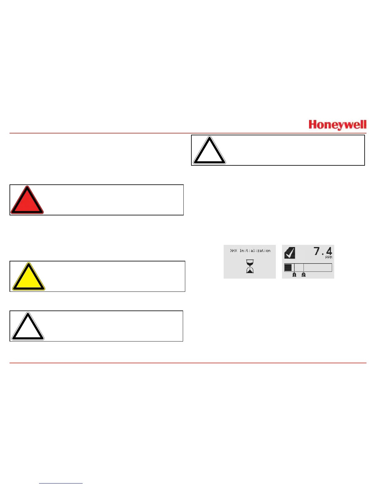
7�Thetransmitterwillenteraboot-uproutinedisplayingthe
initializationscreen�Thetransmitterloadsitsoperating
system,datafromthesensor,sensorsoftwareversion
numbers,gastype,thedetectionrangeandspan
calibrationgaslevel,estimatedtimetonextcalibration
due,andselftestresult�Thiswilltakeabout45seconds�
Figure 62. XNX Initialization and General Status Screens
Inthenalstagesofboot-up,warningsandfaults
maybeobserveduntiltheuserperformstheproper
conguration,calibration,andresetactivities
describedinthefollowingsections�SeeSection5for
descriptionsofwarningsandfaults�
Once theGeneral Status screen appears,the
transmitterandsensorareinnormalmonitoringmode�

 Loading...


