19
7.1.1 Expansion vessel
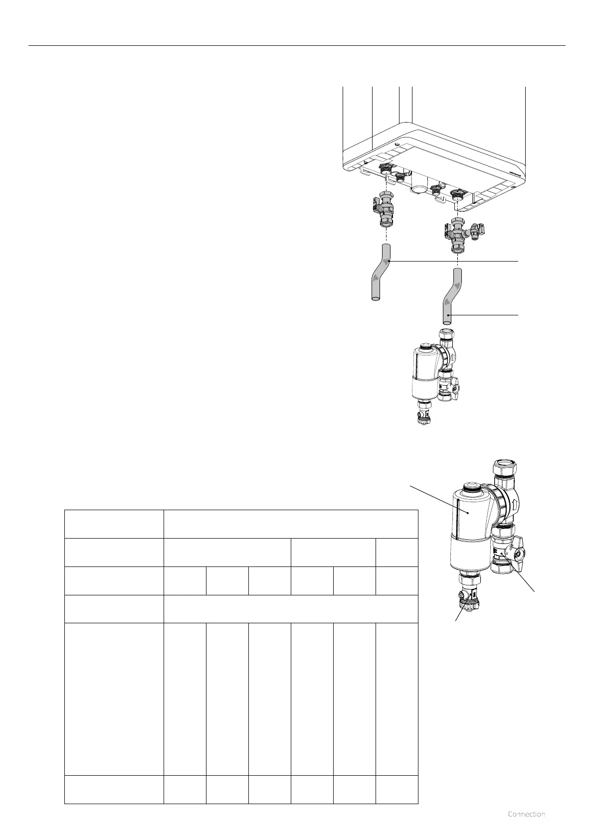
7 CONNECTION
7.1 Connecting to the central heating system circuit
► Flush the central heating system thoroughly as per
BS7593:2019.
► Fit the flow and return pipes to the isolation valves using the
supplied 3/4" fibre washers, noting that the filling link valve
attaches to the return side as per the adjacent drawing.
► The pipework must be correctly supported with full wrap
over type clips / brackets.
► Do not over tighten the connections onto the boiler as
this can cause stress damage and possible internal boiler
leakage.
The CH system should include the following:
► As per BS 7593:2019 a magnetic type filter such as the
Intergas system filter, should be fitted onto the return
pipework as shown in the adjacent diagram.
► When installing the Intergas system filter, the supplied
spigot valve should be fitted to the bottom union to enable
combined isolation with the boiler return valve.
► The drain / dosing valve at the bottom of the filter housing
facilitates the easy draining of the appliance, with the spigot
valve and heating flow valve both closed at the same time.
► A drain tap at the lowest point(s) of the installation.
► A full bore spring loaded single check valve, in the
return pipework nextto the boiler whenever the pipework
rises above the appliance. This prevents the occurrence
of thermosyphoning (radiators getting warm) during DHW
production.
Preformed return pipe
Preformed flow pipe
The appliance is fitted with a expansion vessel adequate for a typical
heating system with 8 radiators installed. For larger volume systems,
an additional expansion vessel must be fitted. Refer to the below
table or contact Intergas for further advice in these cases.
SAFETY VALVE
SETTING (bar)
3.0
VESSEL CHARGE
PRESSURE (bar)
0.75 1.0 1.5
INITIAL SYSTEM
PRESSURE (bar)
1.0 1.5 2.0 1.5 2.0 2.0
TOTAL WATER
CONTENT of SYSTEM
EXPANSION VESSEL VOLUME (litres)
LITRES
25
3.5 6.5 13.7 4.7 10.3 8.3
50
7.0 12.9 27.5 9.5 20.6 16.5
75
10.5 19.4 41.3 14.2 30.9 24.8
100
14.0 25.9 55.1 19.0 41.2 33.1
125
17.5 32.4 68.9 23.7 51.5 41.3
150
21.0 38.8 82.6 28.5 61.8 49.6
175
24.5 45.3 96.4 33.2 72.1 57.9
200
28.0 51.8 110.2 38.0 82.4 66.2
For syst. volumes other than those
given above, mult. the syst. volume
by the factor across
0.140 0.259 0.551 0.190 0.412 0.33
Intergas system filter.
Drain/Dosing
valve.
Spigot isolation
valve
 Loading...


