67
A. Switch o the boiler (see §8.2.1).
A dash
–– will appear on the right display and the central heating
pressure will be visible on the le display.
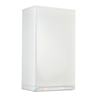
B. Remove the room sealed cover of the boiler by loosening the 2x
5mm Allen key screws (1) and then sliding it up and forward (2).
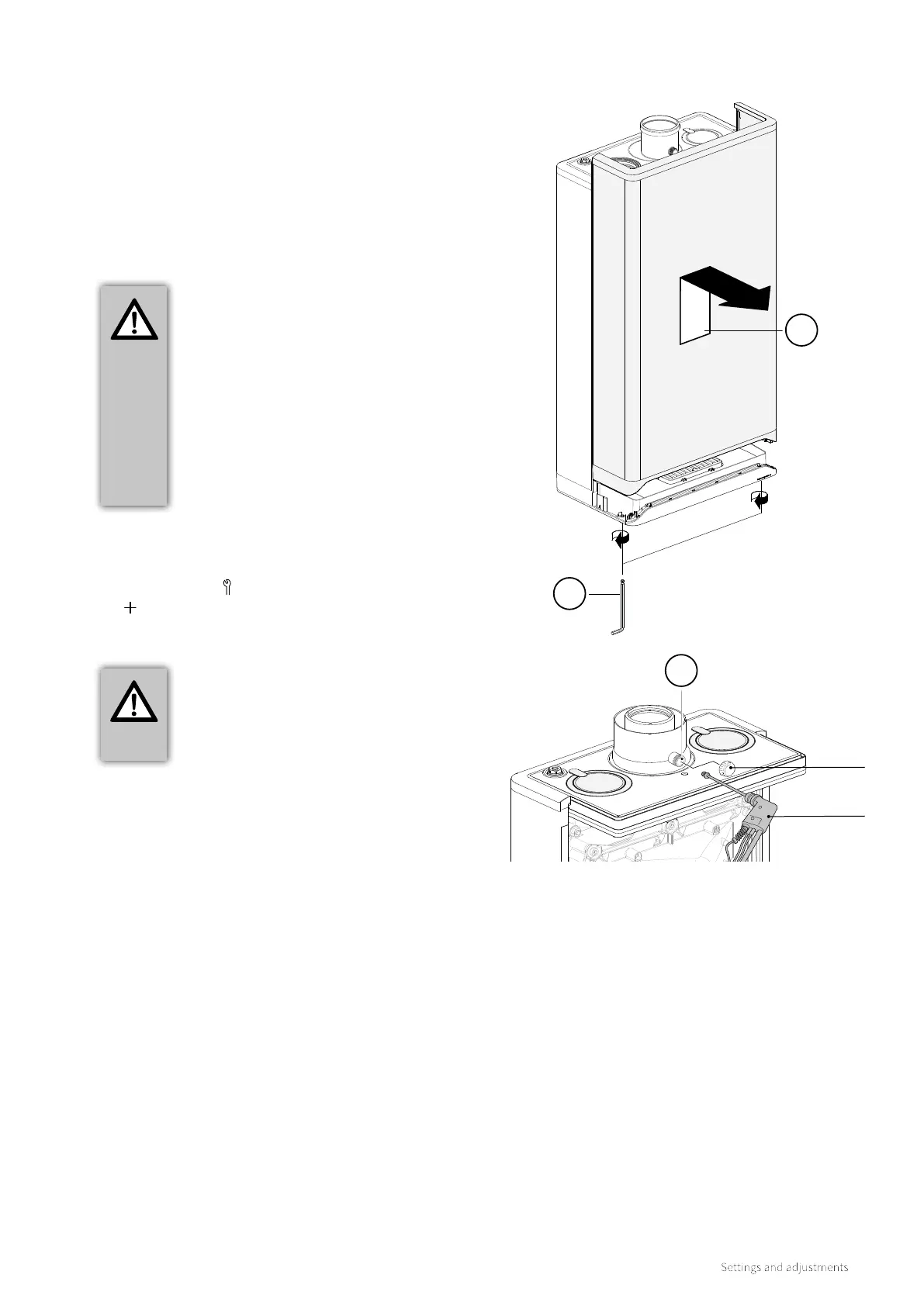
C. Remove the cap of the flue gas sampling test point (3) on the
appliance connector on top of the boiler.
D. Place the sampling probe of the calibrated electronic flue gas
analyser into the flue gas sampling point (3).
IMPORTANT
► Make sure that the flue gas analyser is
calibrated. The start-up procedure of
the flue gas analyser must be completed
before the analyser probe is placed in the
flue gas measurement point.
► The analyser probe must completely seal
o the flue gas measurement point to
provide a reliable measurement.
► The end of the analyser probe must be
located entirely in the flue gases (middle
of the flue gas pipe).
IMPORTANT
► Make sure that the capital letter HH
appears on the right display. This
provides assurance that the boiler is
operating as maximum load.
E. Switch on the boiler by touching above the power light for 2
seconds.
F. Switch on the boiler to maximum output. To do this, hold the
Service symbol and at the same time tap the Plus symbol
twice until the capital letter HH appears on the right display.
G. Wait until the readout of the flue gas analyser is stable (at
least 10 minutes).
H. Note the measured CO
2
(H) value.
CO
2
(H) = measured maximum output CO
2
value
I. Check according to Table 2 whether the measured
maximum output CO
2
(H) % is between the indicated upper
and lower limits.
9.10 Inspection of the gas air control valve
9.10.1 Measuring the flue gas at maximum output
1
2
Cap
Flue gas
analyser
3
 Loading...


