32
7.3 Electrical connection
7.4 Gas connection
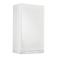
To gain access to the electrical connections or PCB:
► Remove the front panel (see §6.2.2) and pull the PCB
housing forward; then tilt it downwards.
► Consult the electrical schematic in §12.1 for all boiler
connections.
► Aer the desired connections have been made, slide the
PCB housing back into the boiler (until the le and right
safety clips are locked) then replace the front room sealed
cover on the boiler; see §6.2.2.
► Aer making the desired connections re-establish the power
supply to the boiler.
CAREFUL
► The Xclusive complies with IPX4D water
ingress protection. Any cables routed
through the PCB housing must have
grommets or glands fitted to ensure this
integrity is maintained.
CAREFUL
► A fused spur must be located no more
than 1 metre from the appliance.
► For installation within a moisture bound
area i.e a bathroom or kitchen then
please consult the current electrical
regulations for safe separation distances.
► When working on the electrical circuit
always isolate the 230v supply.
► Should the mains power cord be
replaced, this must be ordered directly
from Intergas.
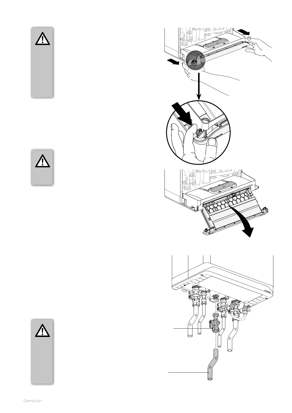
► Using the supplied gas isolation valve & fibre washer
connect the preformed gas pipe to the installation supply
pipework and fully tighten.
► Ensure that the gas pipework is correctly supported with
wrap over type clips.
► Open the main gas valve and boiler isolation valve then
purge the system of air.
► Carry out a full tightness test checking all connections for
any leakage (any leaks must be rectified before proceeding).
CAREFUL
► Before starting any work on the boiler,
always close the gas isolation valve.
► The boiler is intended exclusively to be
installed on a domestic gas supply with a
meter that includes an ECV and pressure
governor.
► When pollution in the gas is to be
expected a gas filter must be placed
in the gas installation pipework to the
boiler.
Gas isolation
valve
22 mm preformed
gas pipe
 Loading...


