EasyManuals Logo

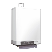
Intergas Xclusive 24 User Manual

Intergas Xclusive 24
92 pages
To Next Page IconTo Next Page
To Previous Page IconTo Previous Page
Page #28 background imageLoading...
Page #28 background image
28
7.1.10 Y-Plan wiring diagram
X15
(24V=)
X14
X13
(24V =)
X12
(24V =)
X11
(24V =)
N/A
X10
(24V =)
N/A
X8
(230V ~)
X5
(230V ~)
X4
(230V ~)
X3
(230V ~)
X2
(230V ~)
X1
(230V ~)
F1 (3,15 AT)
FUSE
23 1
24V=
230V
Mid position
Zone Valve
V4073A
Room
thermostat
230Vac 3amp
Switched
Fused Spur
Wiring Centre
L
N
HTG on
L N
Cylinder
thermostat
DHW on
2
1
3
1
C
1 2
3 4 5 6 7 8 9 10
DHW o
2
Twin channel
Programmer
EARTH
S/L to BOILER
LIVE
M/V S/L
NEUTRAL
NEUTRAL
LIVE
DHW S/L
HTG S/L
LIVE
SUPPLY
S/L LIVE to BOILER
Note:-
With all wiring diagrams when using a digital type room thermostat the Neutral wire from the
wiring centre (2) to room thermostat (2) will not be required.

Table of Contents

Questions and Answers:

Question and Answer IconNeed help?

Do you have a question about the Intergas Xclusive 24 and is the answer not in the manual?

Intergas Xclusive 24 Specifications

General IconGeneral
BrandIntergas
ModelXclusive 24
CategoryBoiler
LanguageEnglish

Related product manuals