37
7.7 Pipeline lengths
7.7.1 Replacement lengths
7.7.2 Example calculation
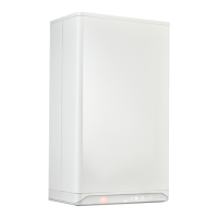
D
D
R
R
R/D = 0,5
R/D = 0,5
Elbow of 90°
R/D=0.5 4 m
Elbow of 45°
R/D=0.5 2 m
C13
C33C53
C33
C13C33
C33
C33 C13
C13C33C53
Boiler Length
Intergas Xclusive 24 100 m
Intergas Xclusive 30 85 m
Intergas Xclusive 36 80 m
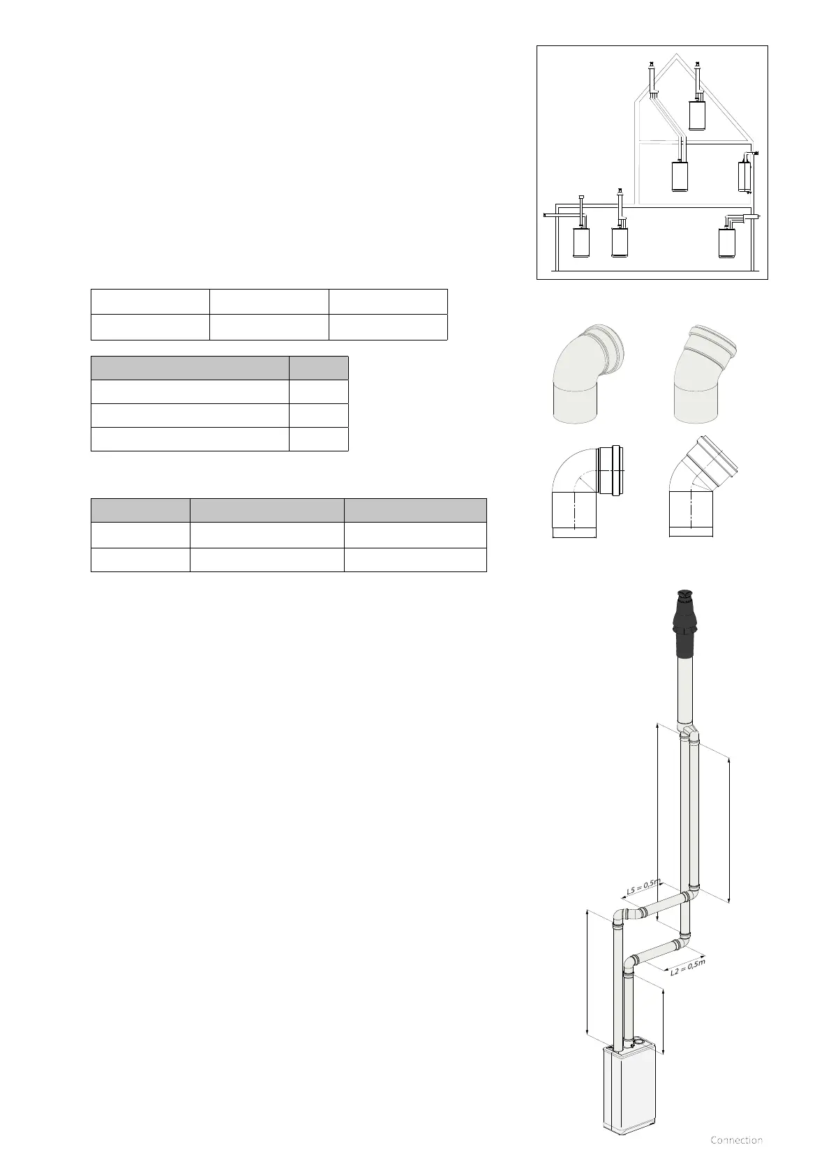
Piping Pipeline length Total pipeline length
Flue L1+L2+L3+(2x4m)
16 m
Air supply duct L4+L5+L6+(2x4m) 16 m
Comments
► The total pipeline length is:
The sum of the straight pipeline lengths + the sum of all the bends
which equates to a total of 33 metres as per the adjacent drawing.
► If the equivalent length of the air supply duct and flue gas duct
combined are less than the maximum permissible quoted then the
twin flue system meets the requirements at this point.
Twin Flue General assembly guide
Flue gas section assembly
► Connect the 80mm vertical adaptor 090767 to the boiler (optional
extra).
► Slide the combustion outlet pipe into the adaptor on the boiler.
► Working from the boiler, slide each extension spigot into the previous
socket and continue with each extension or bend.
► The flue must be bracketed every metre and every change in direction.
► Each bend should have a bracket fitted either side.
► Connect the final section to the chosen terminal outlet.
► The flue gas section must be installed with a fall of 5mm/mtr back
towards the boiler.
Air supply section assembly
► Remove either of the air induction caps by liing the tab and rotating it
anticlockwise by 90 °.
► Slide the first air inlet pipe section into the boiler induction socket.
► Working from the boiler, lide each extension spigot into the previous
socket and continue with each extension and bend.
► The air duct must be bracketed every metre and every change of
direction.
► Each bend should have a bracket fitted either side.
► Connect the final section to the chosen terminal outlet.
► The air supply section must be installed with a fall away from the boiler.
(*Not applicable to vertical flue/air sections)
L6 = 1,5m
L1 = 1m
L4 = 6m
L3 = 6,5m
As the resistance of the flue and air supply duct pipes increases, the
capacity of the boiler will decrease. The allowed decrease in capacity
is a maximum of 5%.
The resistance of the air supply duct and the flue depends on
the length and diameter of the piping system and all associated
components. For each boiler category, the total allowed pipeline
length of the air supply duct and flue is given.
The specification of the pipeline length in metres assumes Ø80
mm piping.
 Loading...


