24
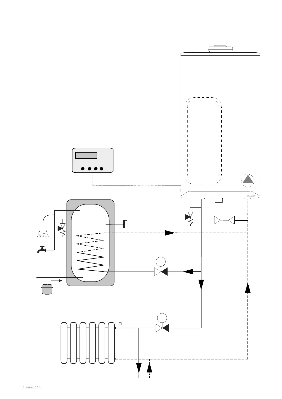
7.1.6 S-Plan zone hydraulic diagram
m
m
A
B
C
D
Built in 6 ltr
expansion vessel
ErP modulating
pump
Stainless steel unvented cylinder
(storage capacity to be established by the installer
Additional expansion
vessel option see §7.1.1
CH circuit
E
F
G
Key to Hydraulic & Wiring diagrams
A. Honeywell V4043H DHW Zone valve (Normally closed)
B. Honeywell V4043H Heating Zone valve (Normally closed)
C. Twin channel Programmer
D. Cylinder overheat thermostat (manual reset)
E. Pressure relief valve (3 Bar)
F. T/P safety (8 Bar)
G. Expansion vessel (potable)
H. System By-pass (Should be 3 meters from boiler connections)
See §9.5 for minimum permissible water circulation through the
boiler heat exchanger.
► To alter the boiler from a combi to a system boiler please see
section §9.1.5 & §9.3
Parameter P001 change to "option 3"
Parameter P010 change to required system output %
(example 30kW set P010 to 50(%) = 15kW output)
H
 Loading...


