27
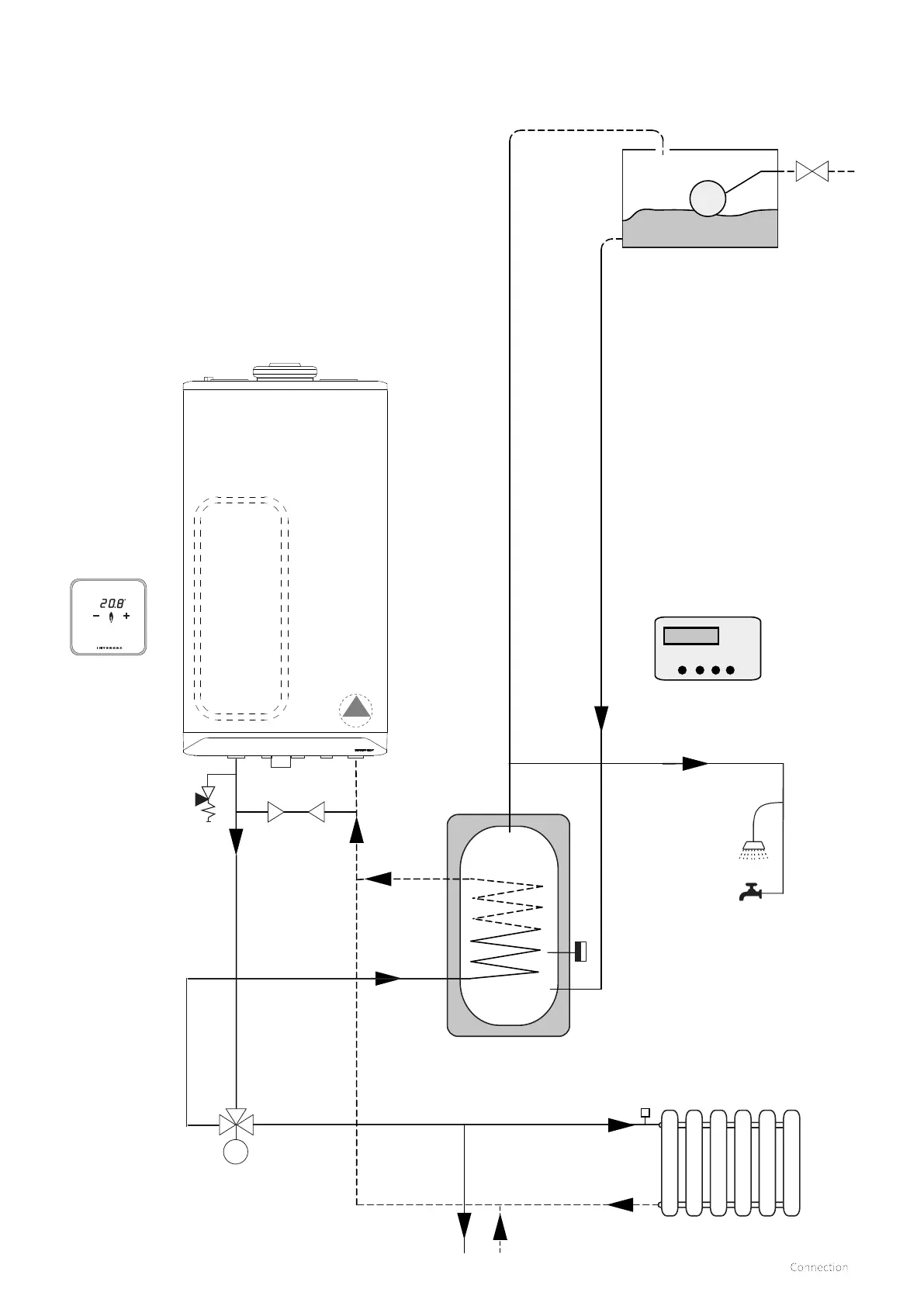
7.1.9 Y-Plan zone hydraulic diagram
m
A
B
C
Built in 6 ltr
expansion
vessel
ErP
modulating
pump
Open vented cylinder
(storage capacity to be established by
the installer
CH circuit
E
F
G
D
H
B
A
AB
Key to Hydraulic & Wiring diagrams
A. Room thermostat
B. Twin channel programmer
C. Cylinder thermostat
D. Boiler pressure reflief valve (3 Bar)
E. Hot water draw o (Gravity)
F. Mid position zone valve
G. Cold feed and expansion tank
H. System By-pass (Should be 3 meters from boiler connections)
► To alter the boiler from a combi to a system boiler please see
section §9.1.5 & §9.3
Parameter P001 change to "option 3"
Parameter P010 change to required system output %
See §9.5 for minimum permissible water circulation through the boiler
heat exchanger.
 Loading...


