FX-3R Maintenance Guide
8-23
8-4-2. Replacing the Outer Bank PCB and Connector Cable
The bank PCB and connector cable are replaced in the same manner as described for the
replacement table for ETF. To do so, see the sections below.
1) Replacing the bank PCB → 8-3-3
2) Replacing the connector cable → 8-3-4
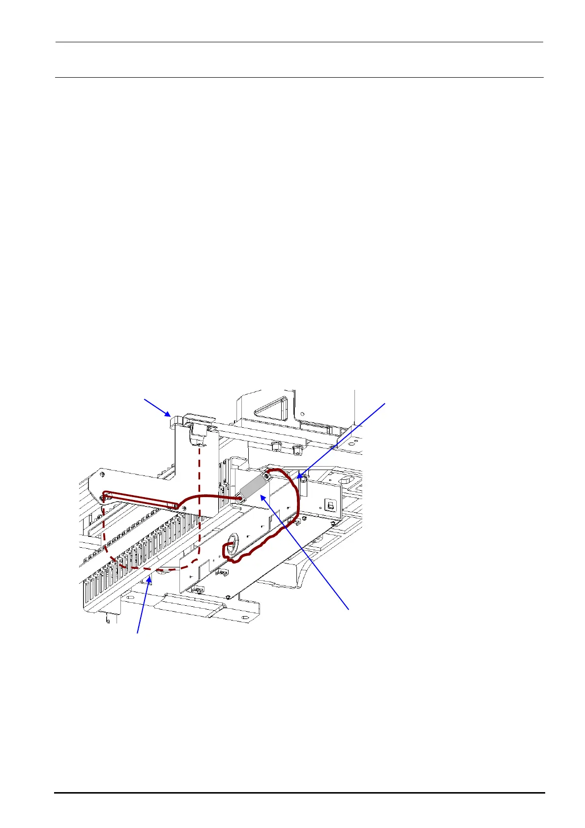
8-4-3. Replacing the Connector for Off-line Setup
1) Disconnect the connector for the off-line setup from the E trolley cover R.
2) Disconnect the connector connecting the cable of the connector for the off-line setup and the
relay cable to the electric bank PCB (right side surface of FDC bracket). After that, replace the
connector for the off-line setup.
3) Reassemble the components in the reverse order of disassembly.
4009
Rev. 1.00
40084837
EF setup cable 2 assembly
Connect the connector on the side
surface of the FDC bracket.
5351
e stay
40084841
EF setup cable 1 bracket assembly
∗ Adjust the length of the dotted portion to 650 mm.
Tape guid
8-4-4. Replacing the ETF Incorrect Insertion Detection Sensor
For details, see section 8-3-6, Replacing the ETF Incorrect Insertion Detection Sensor
(Replacement Table for Electric Feeder).

 Loading...


