FX-3R Maintenance Guide
5-4
Rev. 1.00
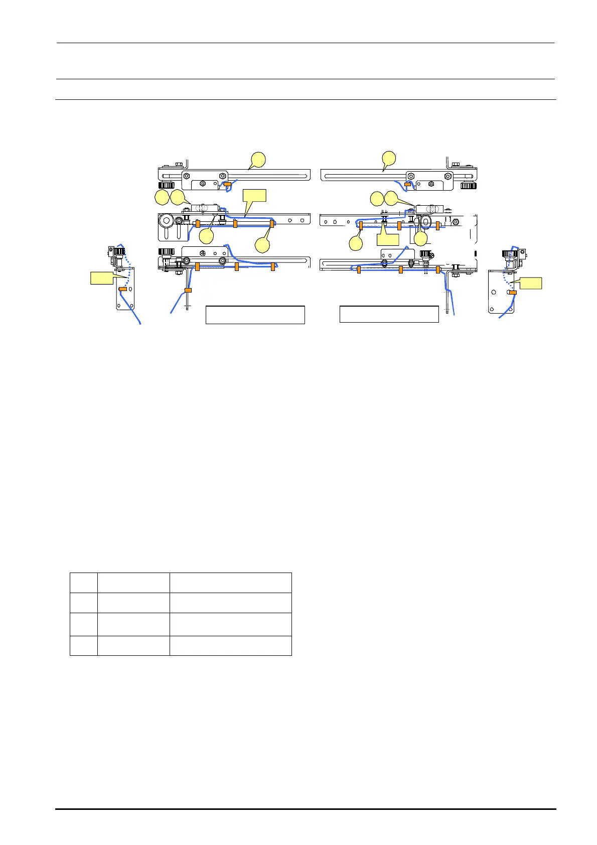
5-4. Replacing the IN and OUT Sensors
Bind the cables A and B with binding bands, taking care that they are not pulled or loosened
excessively during adjustment of sensor position.
Figure 5-4-1 IN and OUT Sensors
<Adjusting the sensitivity>
1) Make an adjustment so that a (matte) black glass epoxy PWB placed on the transport path can
be detected.
2) Place a (matte) black glass epoxy PWB under the sensor and rotate the sensitivity adjustment
knob of the sensor counterclockwise. Then gradually rotate it clockwise up to the position at
which the specified PWB is detected.
∗ If any black glass epoxy PWB is not available, use the PWB having the darkest color of those to
be used.
[List of Replacement Parts]
d
40002208
IN sensor assembly
e
40002210
OUT sensor assembly
f
SL4031291SC
SEMS cap bolt, M3×12
g
EA9500B0000
Tie-up band 60
Table 5-4-1 IN and OUT Sensors
d
c
f
g
e
A
B
Left-side sensor
d
e
c
g
f
B
A
Right-side sensor

 Loading...


