FX-3R Maintenance Guide
3-11
3-5. Replacing the Head Board
3-5-1. Replacing the Head Main Board
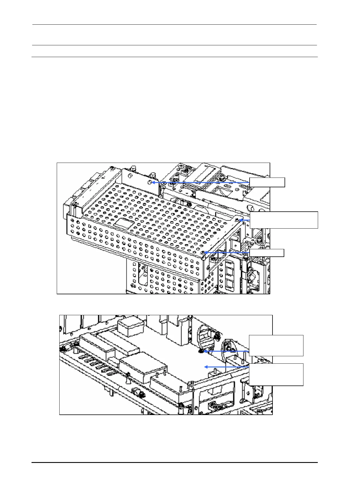
1) Remove the round screws c (×6) and clamps d (×2) to detach the main cover.
2) Disconnect various connectors and remove the SEMS cap bolts e (×6) to detach the head
main board.
3) Reassemble the parts and components in the reverse order of disassembly.
Since the head main board is delivered after it has been adjusted correctly, no adjustment work
is required.
∗ Follow the steps stated inHead Vacuum Level and Temperature Sensor Output Levelon
page 1-4 for the QA table, only if any fault is found.
c SM3040652TN
Round screw M4×6
Clamp d
Main cover
Figure 3-5-1-1 Main Cover
e SL4030691SC
SEMS cap bolts
M3×6
40047506
Head main board
assembly
Figure 3-5-1-2 Replacing the Head Main Board
Rev. 1.00

 Loading...


