FX-3R Maintenance Guide
13-34
13-7. Transport Unit
13-7-1. Structure of Transport Unit
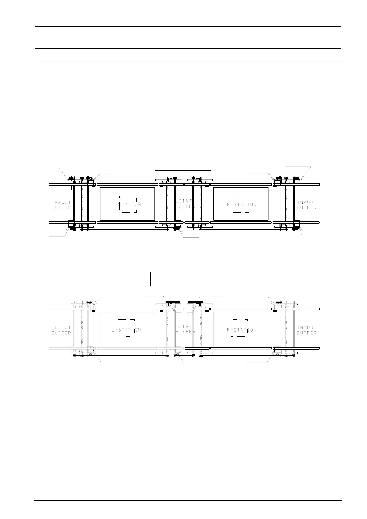
Table 13-7-1-1 shows the structure drawing of the transport unit.
The BASE-CARRY board is mounted at the front right portion under the base frame and the driver
for the stepping motor (for transport, auto PWB width adjustment, and backup) is mounted at both
the front left and right portions.
It is not necessary to change the connection destination boards of the transport L motor, transport
R motor, transport L sensor, transport R sensor, and WAIT sensor inside the transport unit
according to the reference and flow direction.
BU モータ L BU モータ R
L specification
XL specification
BU モータ L BU モータ R
Trans
ort moto
AWC motor L
(For L-STA)
Transport motor
(For IN/OUT)
(For joint)
Transport motor
(For R-STA)
AWC motor R
Transport motor
For IN/OUT
Transport motor
BU motor L BU motor R
[F side]
[F side]
BU モータ L BU モータ R
Trans
ort moto
AWC motor L
(For L-STA)
(For IN/OUT)
(For joint)
Transport motor
(For R-STA)
(For IN/OUT)
BU motor L
BU motor R
AWC motor R
Transport motor
Transport motor
Transport motor
Figure 13-7-1-1 Transport Unit
Rev. 1.00

 Loading...


