FX-3R Maintenance Guide
13-33
13-6-2. LED Indications
Nine LEDs are mounted on the Zθ-servo amplifier.
These LEDs show the status of each axis as described below. The following shows the
correspondence among each axis and LEDs.
Table 13-6-2-1 Zθ-Driver LEDs
No. LED name Indication color
Operation
1 CHARGE Lights up when any electric charge exists in the main circuit.
2 RD1 Green
3 AL1 Red
Shows the status of axis No. 1 (L2θ-, L4θ-, and L6θ-axis).
For details about the status expressed by the combination of RD1 and
AL1, see the Table below.
4 RD2 Green
5 AL2 Red
Shows the status of axis No. 2 (L2Z-, L4Z-, and L6Z-axis).
For details about the status expressed by the combination of RD2 and
AL2, see the Table below.
6 RD3 Green
7 AL3 Red
Shows the status of axis No. 3 (L1θ-, L3θ-, and L5θ-axis).
For details about the status expressed by the combination of RD3 and
AL3, see the Table below.
8 RD4 Green
9 AL4 Red
Shows the status of axis No. 4 (L1Z-, L3Z-, and L5Z-axis).
For details about the status expressed by the combination of RD4 and
AL4, see the Table below.
The following shows the operation status expressed by the combination of RD∗ and AL∗.
Table 13-6-2-2 Combination of Zθ-Driver LED Lighting and Flashing Statuses
RD∗ AL∗
Status
Flashing Flashing
Controller is not connected (immediately after
the power has been turned ON).
Flashing Off
Servo is OFF.
Lit Off
Servo is ON.
Off Flashing Warning occurs.
Off Lit
Alarm occurs.
Lit Lit
S/W installation status
Off Off
Control power is OFF.
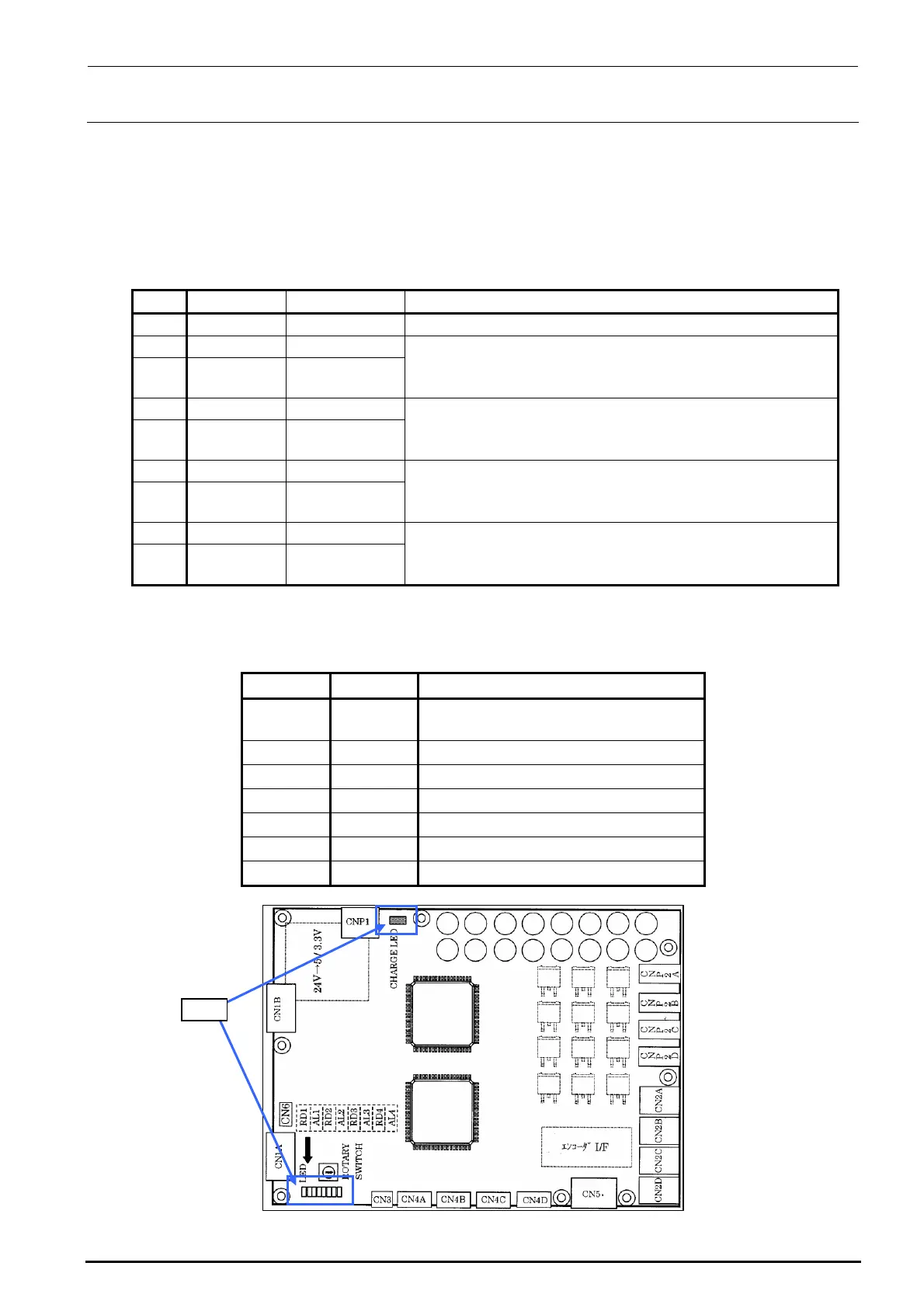
LED
Figure 13-6-2-1 LEDS of the Z/θ amplifier
Rev. 1.00

 Loading...


