FX-3R Maintenance Guide
13-47
13-8. Head Unit
13-8-1. Adjusting the Boards of the Head Unit
13-8-1-1. Adjusting the Head Main Board Assembly
See “Head Vacuum Level and Temperature Sensor Output Level” on page 1-10 for the QA table.
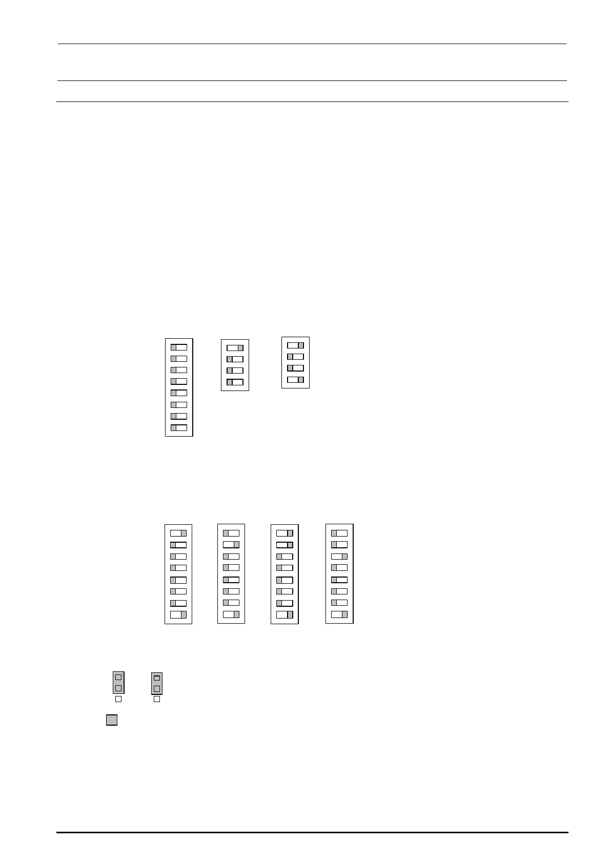
13-8-1-1-1. Switch Settings
The switches have already been set corresponding to the status of the board assembly. Check
the contents described below.
Additionally, the SW4 settings may vary depending on the head position. Set the SW4
corresponding to the head position.
・
SW1, SW2, SW5
・
SW3
・
SW4
・
W4, W5
Check that the W4, W5 are set as described below.
*
portion shows the switch set position and receptacle mounting position.
Check that the SW1, SW2, SW5 are set as described below.
Function Rev. and pattern Rev. of the board are set on the SW 2. Normally, do not change the switch
settings.
The SW4 setting may vary depending on the head position. Check that this switch is set as follows
according to the heat position.
O
N
1
SW1
2
3
4
5
6
7
8
O
1
SW2
2
3
4
SW4
O
N
1
2
3
4
5
6
7
8
O
N
1
SW4
2
3
4
5
6
7
8
L
O
N
1
SW4
2
3
4
5
6
7
8
R
O
N
1
SW4
2
3
4
5
6
7
8
RR
O
1
SW5
2
3
4
W4
1
2
3
W5
1
2
3
Rev. 1.00

 Loading...


