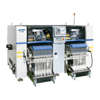
FX-3R Maintenance Guide
i
Rev. 1.00
[1] X-Y UNIT.................................................................................................1-1
1-1. Replacing the Magnescale .....................................................................................1-1
1-1-1. X-Axis Magnescale Affixing Position.................................................................................... 1-2
1-1-2. Y-Axis Magnescale Affixing Position.................................................................................... 1-3
1-1-3. Clearance of the Magnescale .............................................................................................. 1-4
1-1-4. Re-obtaining the Parameters after Replacement of the Magnescale................................... 1-4
1-2. Replacing the Limit Sensor and Origin Near Sensor ..............................................1-5
1-2-1. Replacing the X+/− Limit Sensor and X-Near Sensor .......................................................... 1-5
1-2-2. Replacing the Y +Limit Sensor and YB-Near Sensor........................................................... 1-6
1-2-3. Replacing the X-axis Interference Sensor (Y-C Sensor)...................................................... 1-7
1-3. Replacing the Cable Bear.......................................................................................1-8
1-3-1. Replacing the X-Axis Cable Bear......................................................................................... 1-8
1-3-2. Replacing the Y-Axis Cable Bear......................................................................................... 1-9
1-4. Replacing the Roller Lubrication Part ...................................................................1-10
[2] HEAD UNIT.............................................................................................2-1
2-1. Replacing and Adjusting the Head .........................................................................2-1
2-2. Replacing the Motor ...............................................................................................2-7
2-2-1. Replacing the Z-Motor ......................................................................................................... 2-7
2-2-2. Replacing the θ-Motor.......................................................................................................... 2-9
2-3. Replacing the Laser Sensor (LNC60)...................................................................2-10
2-4. Replacing the Head Up Cylinder ..........................................................................2-11
2-5. Replacing the Belts...............................................................................................2-12
2-5-1. Replacing the Timing Belt Z............................................................................................... 2-12
2-5-2. Replacing the Timing Belt θ ............................................................................................... 2-12
2-6. Replacing the Z-Slide Shaft ..................................................................................2-13
2-7. Readjustment After Replacement of Head Unit ....................................................2-14
[3] PARTS AROUND THE HEAD.................................................................3-1
3-1. Replacing the Solenoid Valves ...............................................................................3-1
3-2. Replacing the Filter.................................................................................................3-3
3-3. Replacing the Bad Mark Sensor .............................................................................3-4
3-3-1. Sensor Assembly .................................................................................................................3-4
3-3-2. Adjusting the Sensor Height................................................................................................. 3-5
3-3-3. Amplifier............................................................................................................................... 3-5
3-3-4. Assembling the Fiber Unit to the Amplifier ........................................................................... 3-6
3-3-5. Amplifier Setting................................................................................................................... 3-7
3-3-6. Manual Setting Method for the F70R Fiber Sensor Amplifier............................................... 3-8
3-4. Replacing the HMS.................................................................................................3-9

 Loading...