FX-3R Maintenance Guide
13-16
13-4. Control Unit
13-4-1. Structure of Control Unit
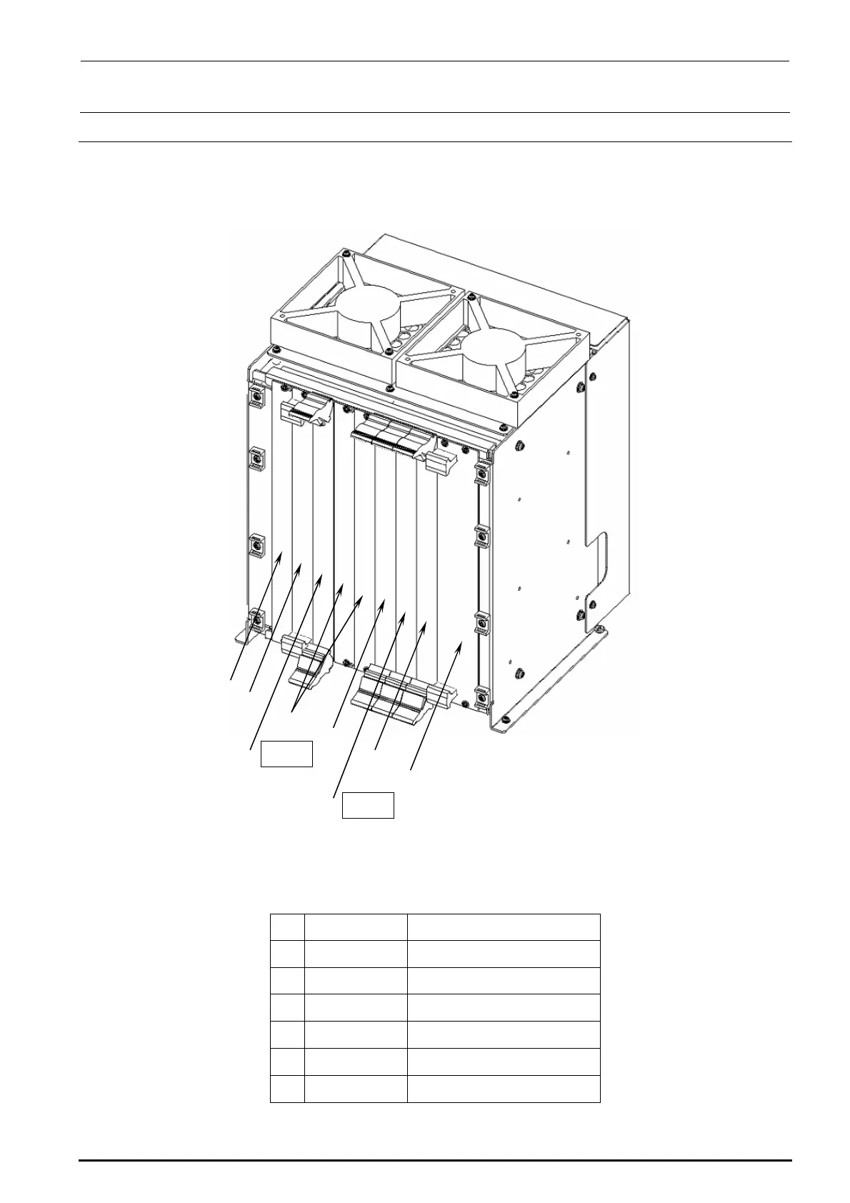
Figure 13-4-1-1 shows the board layout drawing of the control unit. Check that the boards are
mounted correctly while referring to these figures.
c
h
g
e POS2
h
f
e POS1
d
Figure 13-4-1-1 Board Layout Drawing (FX-3R)
Table 13-4-1-1 Boards Used for Control Unit
Part No. Part name
c
40107342 CPU BOARD
d
40048066 ETHER MAIN BOARD
e
40044540 POSITION BOARD
f
40048003 cPCI-8994
g
40047528 IP-X5 PCB ASM
h
E1649729000 BLANK PANEL B
Rev. 1.00

 Loading...


