FX-3R Maintenance Guide
2-9
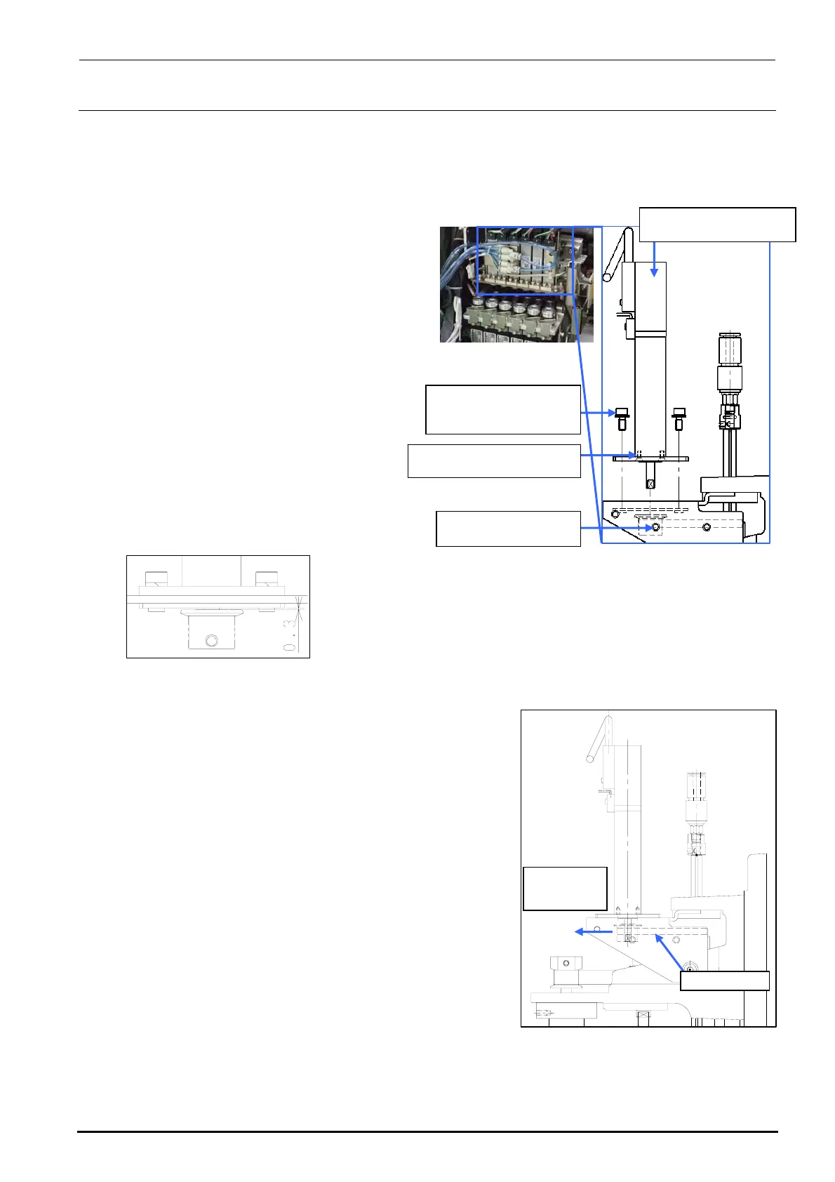
2-2-2. Replacing the θ-Motor
After the θ-motor has been replaced, it is absolutely necessary to re-input the MS parameters
related to the axis home. (For details of input items, see section 2-7.)
1) Disconnect the motor cables from the
servo amplifier board.
(See also steps 2), 3), 8), 9), and 10)
stated in section 2-1.)
Rev. 1.00
2) Loosen the set screws c (hollow set
screws (×1)) of the T pulley.
3) Remove the motor mounting screws d
(SEMS cap bolts (×4)) and pull out the
pulley to detach it.
4) Remove the flat head screws e (×2)
and detach the TM flange.
5) Reassemble the components in the
reverse order of disassembly.
∗ Apply Loctite 242 to the flat head
screws e and tighten them with a
tightening torque of 0.14 N・m.
c SM8030312TP
Set screw M3 L=3
40044533
Servomotor 10W (θ-axis)
SM1020501SC
Flat head screws M2 L=5
6) Follow the steps below to adjust the belt
tension.
<Belt tension adjustment procedure>
c Make a ring using a tie-up band or belt at the top end
of the T pulley of the θ-motor. Hang the bar tension on
this ring. With the bar tension kept pulled with a force
of 12.7N (1.3kgf), secure the T pulley using the
mounting screws.
Tension meter set value (For check)
• Tension meter input value
Weight: 0.9g/m Width: 4.0mm Span: 38.2mm
• Specification value: 6.5±1N
∗ Apply Loctite 242 to the θ-motor mounting screws (2
pcs.) and tighten them with a tightening torque of 2.3
N・m.
∗ When tightening the setscrew of the T pulley, make
sure to align the orientation of the flat part of the
θ-motor shaft and the setscrew of the pulley. Tighten
the setscrew with a torque of 0.5 N・m.
Timing belt T
Pull by the
force of 12.7N
(1.3kgf)
Figure 2-2-2-2 Adjustment of
the θ-motor Belt
Tension
Assemble so that the clearance
between the T pulley and TM nut
plate is 0.3 mm.
d SL6030842TN
SEMS cap bolt with
washer M3×8
Figure 2-2-2-1 θ-motor
e

 Loading...


