FX-3R Maintenance Guide
5-18
Rev. 1.00
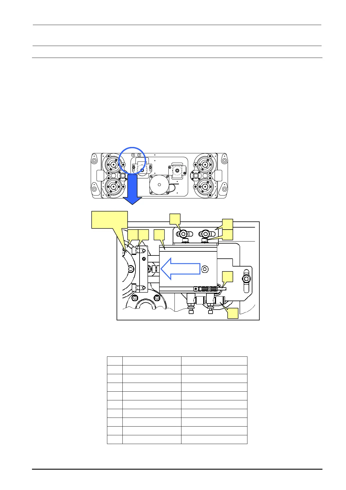
5-13. Replacing the Backup Stopper (for EN Type Only)
1) Loosen the BU stopper bracket set screw h with the air turned ON to adjust the crosswise
position of the BU stopper. Loosen the air cylinder set screw f and make the adjustment so
that the height of the BU stopper (rubber part) c is matched with the height of the flange outer
periphery of the ball screw. After that, check that the dimension A shown in the right portion of
Figure 5-8-1 is 5 mm.
2) For the lock sensor position of the BU stopper, loosen the BU lock sensor set screw k, move
the sensor from the cylinder retract status in the B direction. After the sensor has been turned
ON (LED goes off), further move the sensor 1 mm and secure it firmly.
3) To adjust the speed controller, loosen the lock nut of the speed controller j, turn the speed
controller 3 rotations from its fully closed position, and then secure it with the lock nut.
Figure 5-13-1 Backup Stopper
[List of Replacement Parts]
Table 5-13-1 Replacement Parts of Backup Stopper (Reference for PWB Positioning Hole)
Part No. Part name
c
40000970 BU_STOPER
d
SM6051002TN SCREW
e
PA150101100 DUAL_AIR_CYRINDER
f
SL6040892TN SCREW
g
40000971 BU_STOPER_BRACKET
h
SL6051492TN SCREW
i
BT0400251EA AIR_TABE
j
PC010508000 SPEED_CONTROLLER
k
40002241 BU_LOCK_CABLE_ASM
cd e f
g
h
j
k
Ball screw
flange
“B” direction

 Loading...


