FX-3R Maintenance Guide
13-3
Rev. 1.00
13-3. Power Supply Unit
13-3-1. Structure of Power Supply Unit
Two power supply units are mounted on the left and right at the rear of the machine. Figure
13-3-1-2-1 and Figure 13-3-1-2-2 show the structure drawings of the power supply unit.
The power supply unit is composed of DC power supplies, control relays, and circuit protectors, and
designed to supply the AC and DC power to the units (control unit, X-Y unit, Z-θ unit, transport
unit, and head unit.)
The following shows the application of each DC power supply.
• +6V (+6.3V to 6.5V, PS1): For controlling of feeder (stacking, 32mm-paper tape)
• +24VA (+24±0.1V, PS2): General-purpose (For control unit outer board, stepping driver, etc.)
• +24VB (+24±0.1V, PS3): For control of Zθ-servo amplifier
• +24VC (+24±0.1V, PS4): For driving of safety circuit (EN machine only)
• +24VC (+26±0.1V, PS5): For EFT power supply
13-3-1-1. Adjusting Method of DC Power Source Voltage Level
Table 13-3-1-1-1 DC Power Source Voltage Level Settings
No.
Power
specifications
Power
symbol
Measurement terminals of power supply unit
Voltage adjustment
value
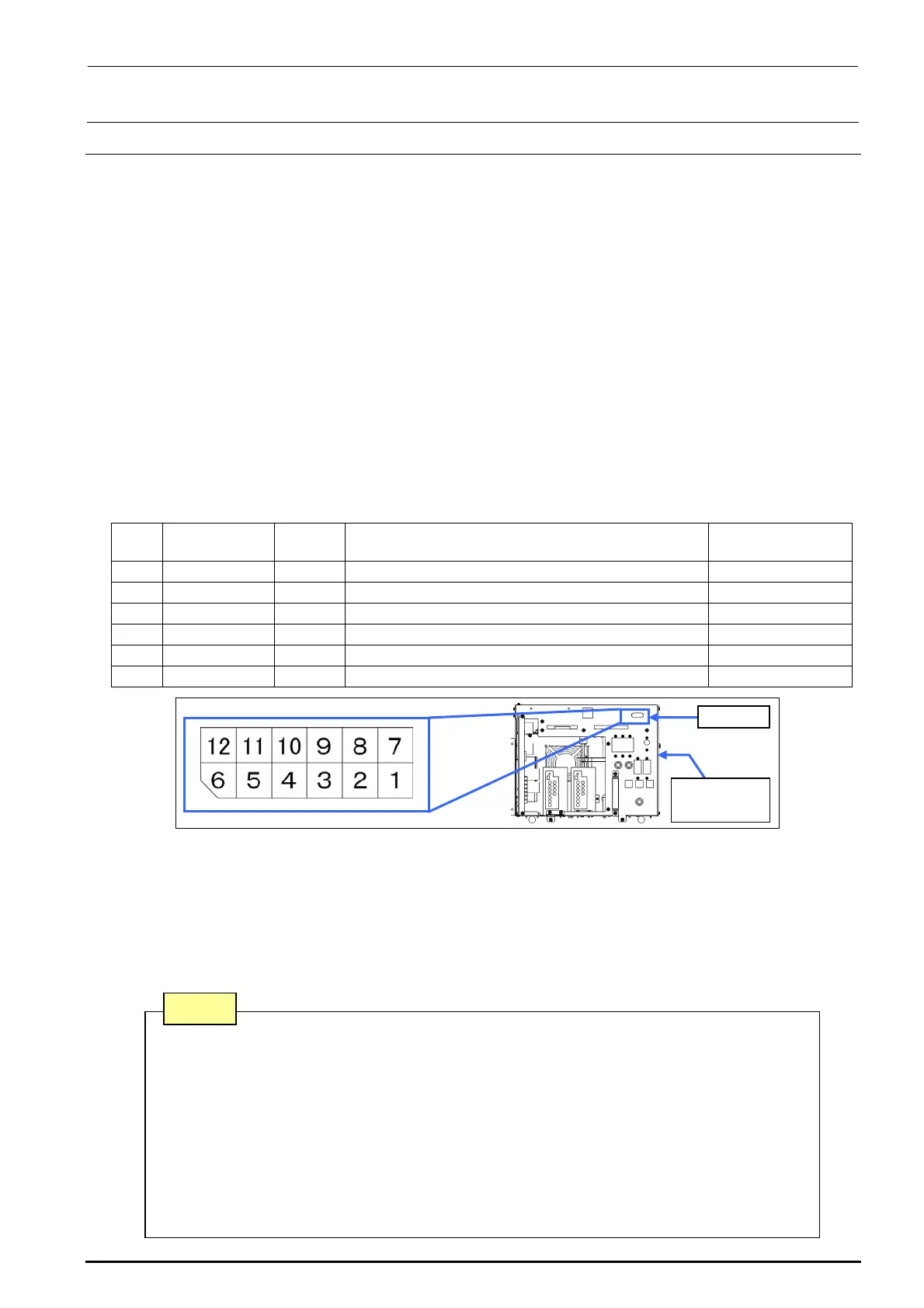
1 (∗) +48V - CN 039 Pin No. 1 (+48V) and Pin No. 7 (+48VRTN) -
2 +6V PS 1 CN 039 Pin No. 3 (+6V) and Pin No. 9 (+6VRTN) (+6.3 to 6.5V)
3 +24V PS 2 CN 039 Pin No. 4 (+24VA) and Pin No. 10 (+24VARTN) (+24V±0.1V)
4 +24V PS 3 CN 039 Pin No. 5 (+24VB) and Pin No. 11 (+24VBRTN) (+24V±0.1V)
5 +24V PS 4 CN 039 Pin No. 6 (+24VC) and Pin No. 12 (+24VCRTN) (+24V±0.1V)
6 +24V PS 5 CN 039 Pin No. 2 (+26V) and Pin No. 8 (+24VRTN) (+26V±0.1V)
Figure 13-3-1-1-1 Power Supply Unit CN039
• The DC power output voltage is to be adjusted on the CN039 (connector on the front of the
power supply unit) of the power supply unit.
• No. 1 with an asterisk (∗) is a power supply line not needing any adjustment.
• Pull out the PSU BRACKETs (PS1, PS3, PS4) or adjust the output voltage potentiometer of each
power supply of the PS2 and PS5 located on the front of the DC power supply so that the DC
power output voltage levels No. 2 to 6 are specified adjustment values.
CN039
Power
supply unit
Note 1. Carefully adjust the variable resistor so that the voltage value does not
exceed the specified adjustment level.
Note 2. Never connect CN039-7 and 8 pins to the GND line of a power supply
unit other than that to be adjusted.
Note 3. PS4 is a DC power supply for the EN specifications mounted on the
POWER UNIT (EN) and is not mounted on the POWER UNIT.
Note 4. Before adjusting the voltage of the PS5, disconnect the connectors of the
electric bank. (Adjust the voltage in the no-load status.)
Note

 Loading...


