FX-3R Maintenance Guide
5-3
Rev. 1.00
5-3. Replacing the STATION, IN, OUT, and JOINT Motors
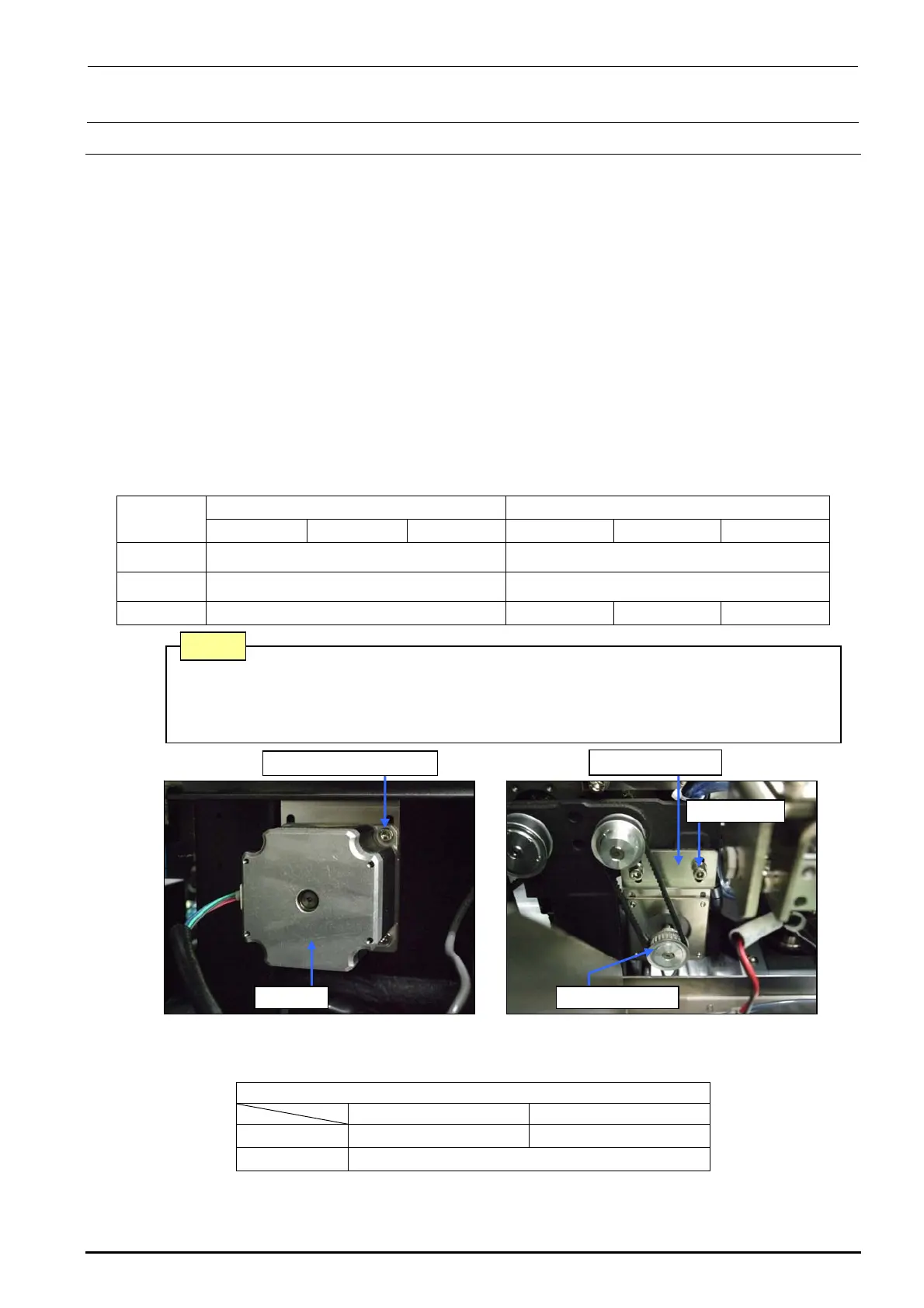
1) Disconnect the connector of the motor relay cable.
2) Loosen the screws f fixing the motor bracket d to detach the drive belt from the motor pulley
e.
3) Loosen the motor fixing screws g and detach the motor c.
Reassemble the parts and components in the reverse order of disassembly. (i.e. from step 3) to step
1)). While reassembling, the following adjustment is required.
<Adjustment> For details, see “PWB Transport” in the QA table.
1) The end face of the motor pulley shall be aligned with the end of the motor shaft.
2) Tension adjustment of the timing belt
• Specification value: 17.5 to 21.5N⋅m
Use UNITTA's acoustic belt tension meter for measurement. Enter the following values
to the tension meter and make a measurement:
Table 5-3-1 Transport Motor Tension Adjustment Values
L specification XL specification
STATION IN/OUT JOINT STATION IN/OUT JOINT
Weight 2.5
←
Width 6.0
←
Span 90 90 182 160
Figure 5-3-1 Station Motor (L specification)
Table 5-3-2 Replacement Parts of Transport Motor
[List of Replacement Parts]
STATION/IN/OUT JOINT
L specification 40048074 ∗1 40048075 ∗2
XL specification 40048075
∗1 The transport motor was changed from the motor (E93417290A0) and these motors have the interchangeability.
∗2 The transport motor was changed from the motor (E93408550A0) and these motors have the interchangeability.
Belt (tension) is stretched excessively. → Torque of the drive shaft increases.
Belt (tension) is loosened excessively. → Teeth on the timing pulley are skipped.
(Noise is produced.)
Note
Motor bracket d
Screws f
Motor pulley e
Motor fixing screw g
Motor c

 Loading...


