FX-3R Maintenance Guide
5-25
Rev. 1.00
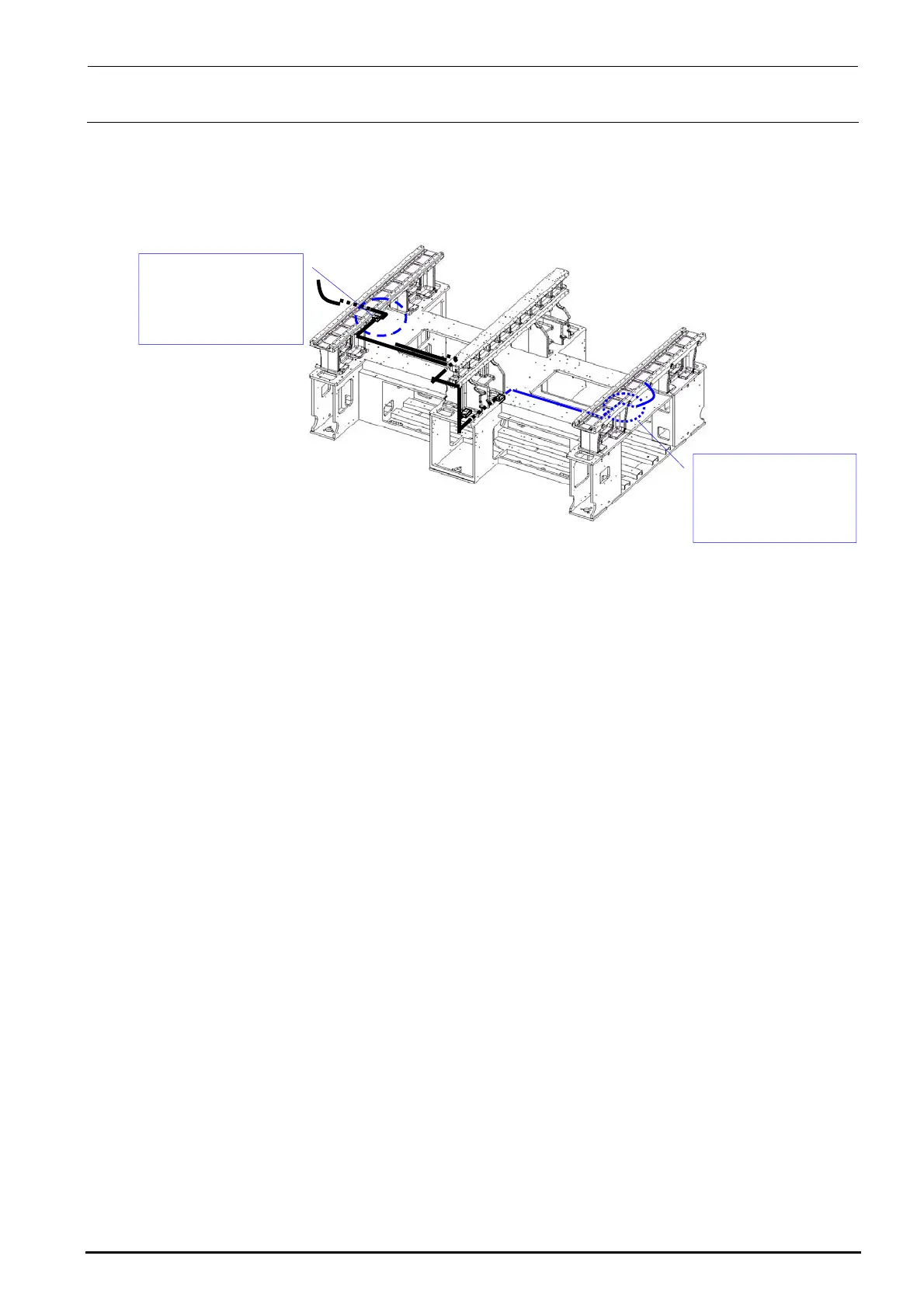
3) Disconnect the BARCODE READER relay connector. (The relay connector is connected to
the relay cable at a position close to that shown in the Figure below.)
The black line shows the cable route for the left → right transport while the blue line shows
that for the right → left transport.
Figure 5-15-3
4) Mount a new BARCODE READER with the flat head screws e while referring to its
orientation.
Connect the relay connector. Bundle the cables, and then run them through the original route.
Relay connector
connection position
(For left → right
transport)
Relay connector
connection position
(For right → left
transport)

 Loading...


