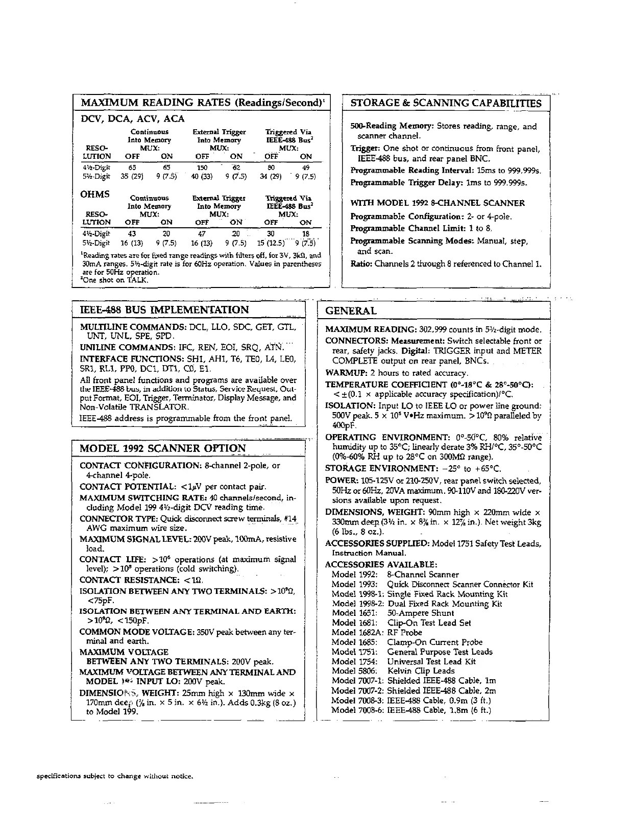
MAXIMUM READING RATES (Readings/Second)’
STORAGE & SCANNING CAPABILITIES
IEEE-488 BUS IMPLEMENTATION
GENERAL
MULTILINE COMMANDS: DCL, LLO. SDC, GET, GTL,
UNT, UNL, SPE. SPD.
UNlLiNE COMMANDS: IFC, REN, EOI, SRQ. ATN.
INTERFACE FUNCIlONS: SHl, AHI, T6, TFQ, L4, LEO,
SRl, RLI. PPO, DCl, DTl, CD. El.
All front pane, functions and programs are available over
the IEEE-488 bus, in addition to Status, Swice Request, Out-
put Format, EOI, Trigger, Terminator, Display Message, and
Non-Volatile TRANSLATOR.
IEEE-488 address is programmable from the front panel.
_ ,I
MAXIMUM READING: 302,999 cmmts in SK-digit mode.
CONNECTORS: Measurement: Switch selectable front or
rear, safety jacks. DigitaL TRIGGER input and METER
COMPLET!? output on rear panel, BNCr.
WARMUP: 2 hours to rated accuracy.
TEMPERATURE COEFFICIENT ,04-18’C & 28’-50’0:
c t(O.1 x applicable accuracy sp&fication)l°C.
ISOLATION: Input LO to IEEE LO or power line ground:
5wV peak. 5 x IO’ V-Hz maximum. > lo90 paralleled by
4wpF.
OPERATING ENVIRONMENT: O”-5O”C, 80% re,ativ&
humidity up to 35°C; linearly derate 3% RH/‘C, 35”.M”C
(0%40% RH up to 28OC on 300MI-i range).
STORAGE ENVIRONMENT: -2Y to +WC.
POWER: IOS-125V or ZlC-25OV, rear panel switch selected,
5oH.z or MIHz, ZOVA maximum. 9UllOV and 180-ZOV MF
sions available upon request.
DIMENSIONS, WSIGKT: 90mm high x 220mm wide x
33hm deep (3% in. x 81 in. x 12% in.). Net weight 3kg
(6 lbs., 8 oz.).
MODEL 1992 SCANNER OPTION
CONTACT CONFIGURATION: 8-channel 2-p&, or
4channel 4pole.
CONTACT POTENTIAL: <lpV per contact pair.
MAXIMUM SWITCHING RATE: 40 channels/second, in-
cluding Model 199 4’/r-digit DCV reading time.
CONNECTOR TWE: Quick disconnect screw ~y$inaIS, X’?~
AWG maximum wire size.
MAXIMUM SIGNAL LEVEL: 200” peak, lM)mA, resistive
load.
CONTACT LIFE: 210’ operations (at maximum signal
level); >I@ operations (cold switching).
CONTACT RESISTANCE: <Xl.
ISOLATION BETWEEN ANY TWO TERMINAL5 >lO%
<75pF.
lSOLATION BETWEEN ANY TERMlNAL AND EARTH:
> 10% < 15OpF.
COMMON MODE VOLTAGE: 35oV peak between any ter-
mhaf and earth.
MAXIMUM VOLTAGE
BETWEEN ANY TWO TERMINALS: 2OOV peak.
MAXIMUM VOLTAGE BEI’WEEN ANYTERMINAL AND
MODEL 19; INPUT Lo: 2oOV peak.
DIMENSIOhi; WEIGHT: 25mm hieh x 13Omm wide x
170mm deep (% in. x 5 in. x 6% ic). Adds 0.3kg (8 0~)
to Model 199.
SO&Reading Memory: Stores reading, range, and
scanner channel.
Trigger: One shot or continuous from front pane,,
IEEE.488 bus. and rear panel BNC.
Programmable Reading Interval: 15ms to 999.999s.
Programmable Trigger Delay: Ims to 999.9995.
WITH MODEL 1992 &CHANNEL SCANNER
Pmgmmmable Configuration: t or 4-pole.
Fmgrammable Channel Limit: 1 to 8.
Pmgnmmable Scanning Moder: Manual, step,
and scan.
Ratio: Channels 2 thmugh 8 referenced to Channel 1.
ACCESSORlES SUPPLIED: Model ,751 Safety Test Leads,
Instruction Manual.
ACCESSORlES AVAILABLE:
Model 1992: B-Channel Scanner
Model 1993:
Quick Disconnect Scanner Conn&tor Kit
Model 199&l: Single Fixed Rack Mounting Kit
Model 1998-2: Dual Fixed Rack Mounting Kit
Model 1651: SO>Ampere Shunt
Model 1681:
Clip-On Test Lead Set
Model 1682A: RF Probe
Model 1685: Clamp-On Curem Probe
Model 1751:
General Purwse Test Leads
Model 1754:
Universal T&t Lead Kit
Mode, 5806:
Kelvin Clip Leads
Model 7W7-1: Shielded IEEE-488 Cable. Im
Model 7007-2: Shielded IEEE-488 Cable, 2m
Model 7008-3: IEEE-488 Cable, 0.9m (3 ft.)
Model 7008.6: IEEE-488 Cable, 1.8m (6 ft.)
specifications +ect to change without “otke.
 Loading...