3: Functions and features Series 2600B System SourceMeter® Instrument
3-28 2600BS-901-01 Rev. B / May 2013
Timers must be used to configure the pulse width and period. Refer to Using timers to perform pulse
mode sweeps (on page 3-45) for details.
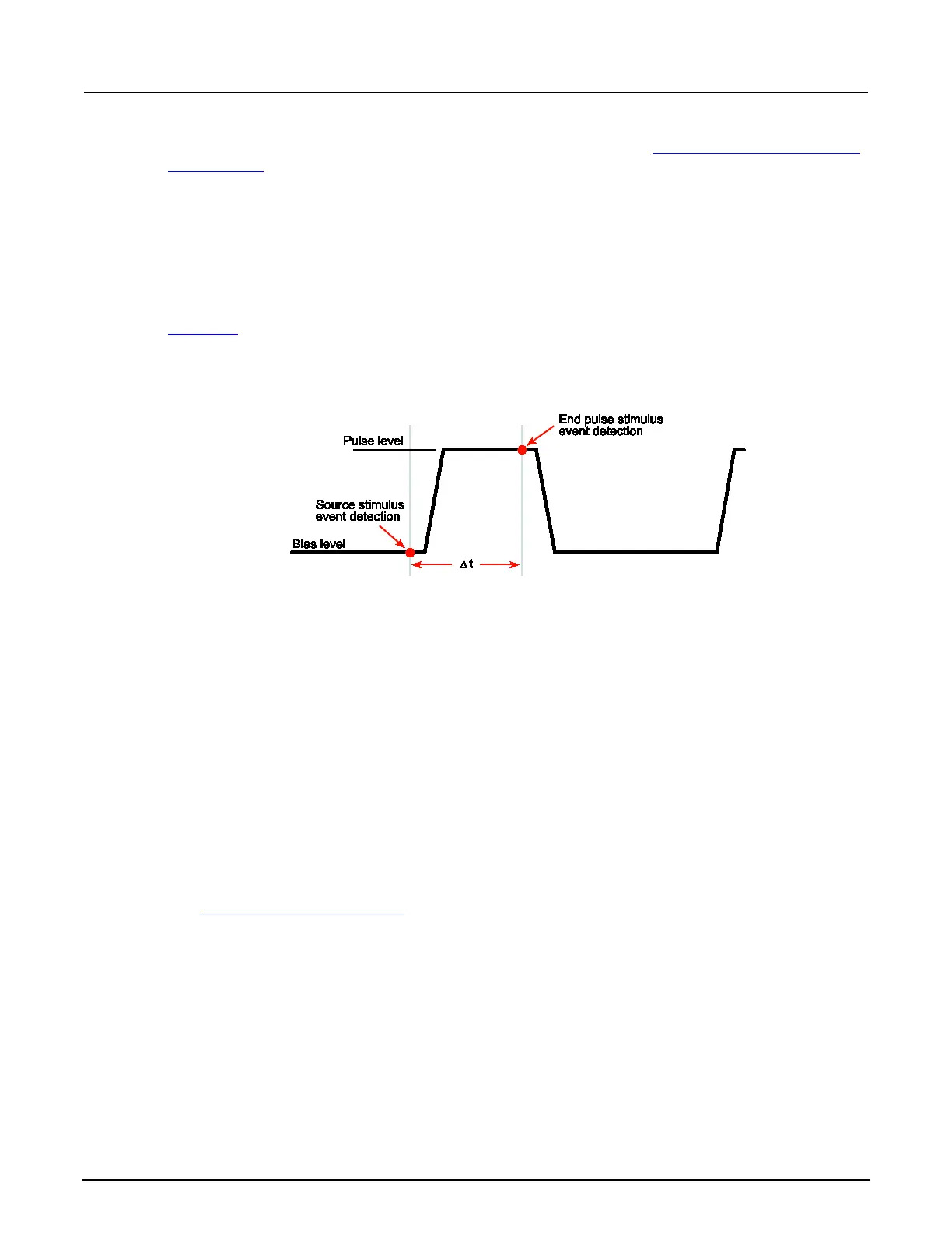
The pulse width is managed by controlling the duration between the source stimulus event and the
end pulse stimulus event. Note that a latency exists between these stimulus events and their resulting
source level transitions. This trigger latency can vary based on factors such as the source range and
the electrical characteristics of the device under test (DUT). The fast ADC mode can be used to
characterize this latency, in order to better control the shape of the pulse under a particular set of test
conditions.
The figure below shows the source and end pulse stimulus events in relationship to the pulse (see
Triggering (on page 3-32
) for information for information on stimulus events). Any change in ∆t will
result in a corresponding change in the pulse width.
Figure 61: Pulse width control
Pulse duty cycle
Duty cycle is the percentage of time during the pulse period that the output is on. It is calculated as
follows:
Duty cycle = Pulse width / (Pulse width + Off time)
For example, if the pulse width is 10 ms and the off time is 90 ms, the duty cycle is calculated as
follows:
Duty cycle = 10 ms / (10 ms + 90 ms)
= 0.10
= 10 percent
See Maximum duty cycle equation (on page 4-3) for additional information on calculating the
maximum duty cycle for a SMU.
 Loading...