Chapter 5 Disassembly and Assembly
5-43
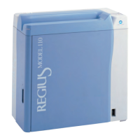
5 Remove the justifier motor.
•
4 screws (M4 x 12)
6 Remove the gear.
•
2 setscrews
7 Install the gear on the new justifier motor.
•
2 setscrews
Fix the gear, fitting the edge surfaces of it and the
motor shaft.
8 See Step 5 to install the justifier motor on the
motor mount board.
•
4 screws (M4 x 12)
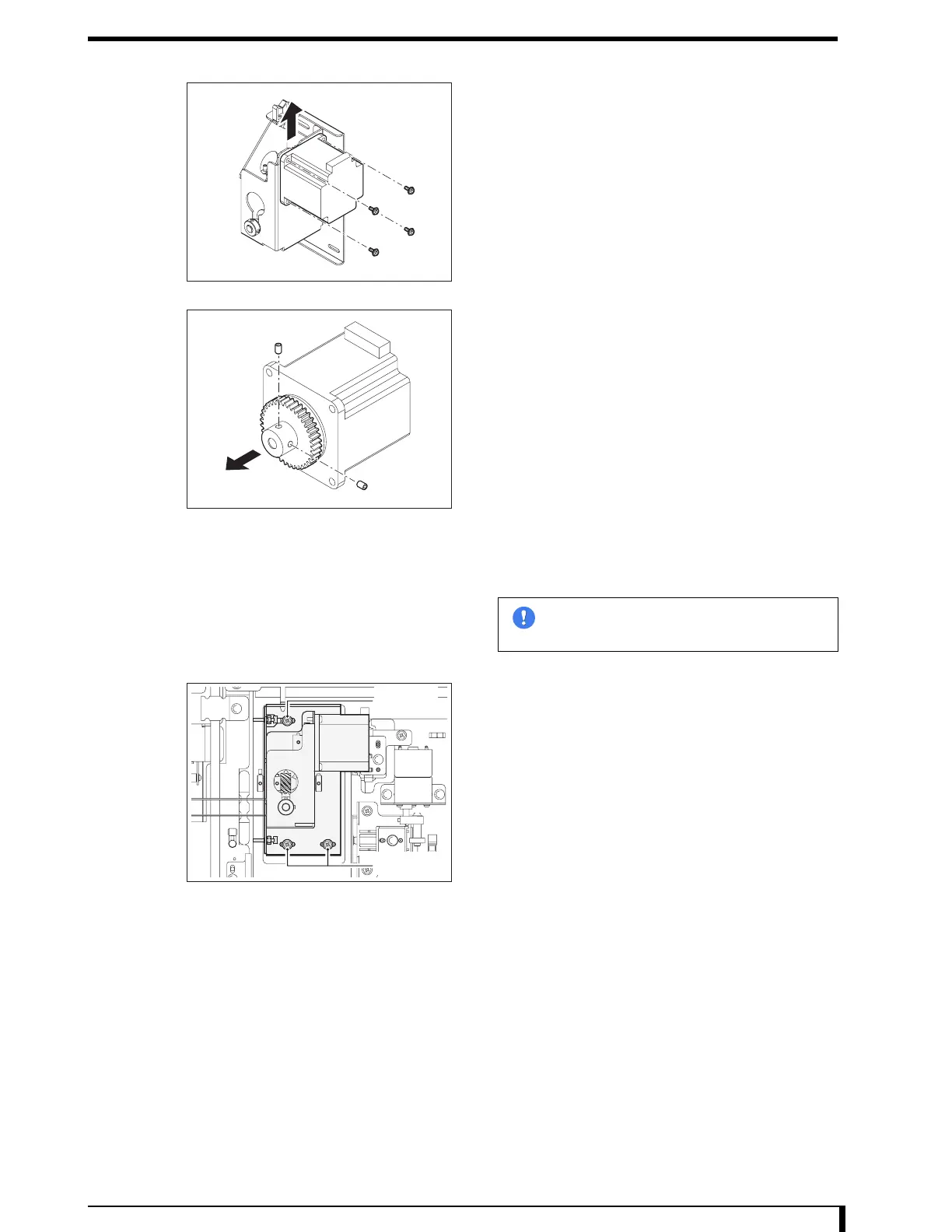
9 Temporarily secure the motor mount board to the
main unit.
•
3 hex/Phillips-head screws (M4 x 8)
10 See "6.1 Adjust Justifier Belt Tension (Page 6-2)"
to adjust the belt tension.
11 Connect the connector (JP50) that was removed
in Step 3.
12 Install the exterior frame (front) that was removed
in Step 2.
•
4 screws (M4 x 8)
13 See " Installation Procedures (Page 5-8)" in "5.2.3 Removing/Installing the Exterior Panel
and Insertion Unit" to install the insertion unit and exterior panel.
Now, you have finished with the procedures to replace the justifier motor.
Im
ortant
Make sure the connector is in the right
direction when installing the motor.
Setscrew
Setscrew
 Loading...