Chapter 5 Disassembly and Assembly
5-45
5 Unplug the cable.
•
Connector (JP44)
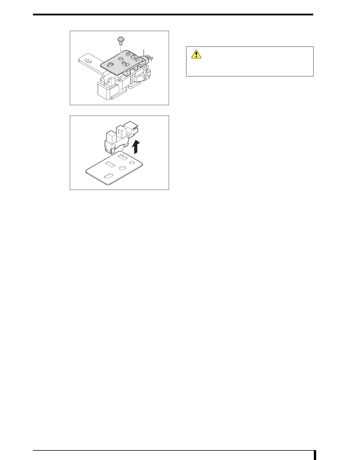
6 Remove the justifier detection mount board 2.
•
1 screw (M4 x 10)
7 Remove the justifier standard sensor.
8 Install the new justifier standard sensor on the
justifier detection mount board 2.
9 See Step 6 to install the justifier detection mount
board 2.
•
1 screw (M4 x 10)
10 Connect the cable that was unplugged in Step 5
to the justifier standard sensor.
•
Connector (JP44)
11 See Step 3 and Step 4 to install the cassette
detection unit assembly.
•
1 hex/Phillips-head screw (M4 x 8)
12 See " Installation Procedures (Page 5-8)" in "5.2.3 Removing/Installing the Exterior Panel
and Insertion Unit" to install the removed exterior panel.
Now, you have finished with the procedures to replace the justifier standard sensor.
JP44
Caution
When removing the connector, hold a notch
on the connector without pulling a cable.
Giving a strong pull to the cable may cause
it to be broken.
 Loading...