Chapter 5 Disassembly and Assembly
5-98
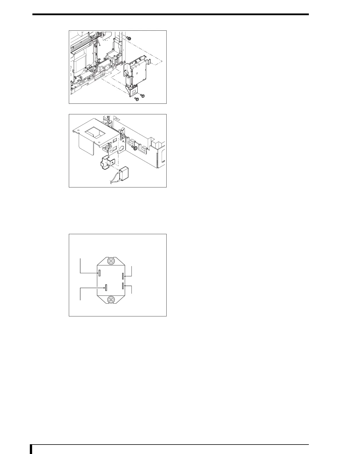
4 Remove the halogen power supply unit assembly.
•
1 hex/Phillips-head screw (M4 x 8)
• 2 screws (M4 x 8)
5 Remove the bracket, then the condenser.
•
1 screw (M3 x 6)
6 Install the new condenser.
•
Bracket
• 1 screw (M3 x 6)
7 Install the halogen power supply unit assembly
that was removed in Step 4.
•
1 hex/Phillips-head screw (M4 x 8)
• 2 screws (M4 x 8)
8 Connect the connectors removed in Step 3 and
fix them using the snap ties and clamps.
•
Ties
• Snap ties at 3 locations
• Interlock relay 2
• 4 pieces (see the figure)
• Standby power supply
• CN1 (JP23: cable)
• CN2 (JP26: cable)
• Halogen power supply
• CN1 (HCN1: cable)
• CN2 (HCN2: cable)
• CN3 (HCN3: cable)
• Condenser
• JJ1A (JP1: cable)
• JP1A (JJ1: cable)
9 Install the electric component mount panel that
was removed in Step 2.
•
8 hex/Phillips-head screws (M4 x 8)
10 See " Installation Procedures (Page 5-8)" in "5.2.3 Removing/Installing the Exterior Panel
and Insertion Unit" to install the first front panel.
Now, you have finished with the procedures to replace the condenser.
First Front Side
(Black)
Interlock
Relay 1, etc.
(Brown)
Interlock Switch
Interlock Relay 2
(Brown)
MDU, etc.
(Blue)
Digital Power Supply
 Loading...