5-2
Repair manual KTM LC8 Art.-No. 3.206.035-E
1
1
A
A
1
1
A
2
3
4
5
6
7
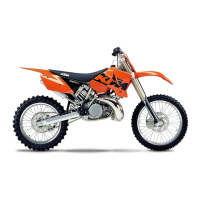
Replacing the roller bearing
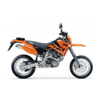
– Remove all bearing locking bolts 1 from both case halves.
NOTE:
– Additional oil jets are installed from the 2005 model; they should
also be removed to prevent them from being bent.
– the output-end antifriction bearing on the countershaft mounted by
KTM does not have a sealing from the 2005 model. An antifriction
bearing with a one-sided sealing is provided for repair; to keep it
from blocking the lubrication, the open side must point towards the
inside (towards the center of the housing).
– Remove all shaft seal rings and the dowel pins from the case halves.
Heat both case halves evenly in an oven at 150° C; the roller bearings
will fall out of the case by themselves. If any roller bearings should be
left in the case, tap the case lightly on a flat wooden surface.
NOTE: the shift shaft bearing
2 must be pressed out with the pressing
tool 600.29.043.030, although this bearing is usually highly resistant
to wear.
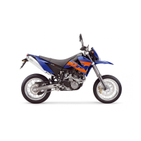
– Replace all of the roller bearings. The new roller bearings can be
inserted by hand until flush as soon as the case temperature has
reached approx. 150° C. The roller bearings should fit tightly after
cooling down. Use a mandrel to carefully press in any bearings that
are not flush with the surface.
NOTE: the shift shaft bearing
2 must be pressed in flush with the
pressing tool 600.29.043.030.
– Press in the shaft sealing ring
3 for the push rod until flush using
the special tool 600.29.043.010.
– Press in the shaft sealing ring for the countershaft
4 until flush
using the special tool 600.29.043.020.
– Press in the shaft sealing ring for the shift shaft
5 until flush using
the special tool 600.29.043.030.
–
Apply Loctite 243 to all bearing locking bolts 1 and tighten to 6 Nm.
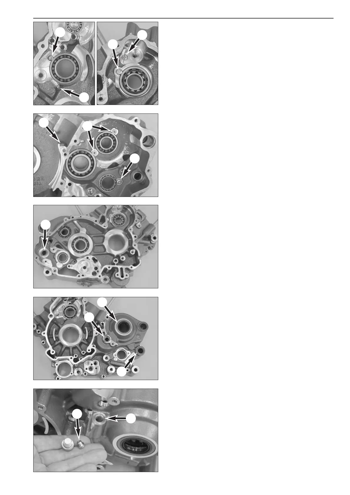
– Remove all of the oil jets, blow compressed air through the oil ducts
and screw the oil jets back on.
NOTE:
– Size "60" jets are used to lubricate the timing chains, size "90" jets
for the piston cooling.
– Starting with engine number 2-600-02549, a size "30" reducing
sleeve
6 is screwed into the outer bore 7 on the outside of the left
housing half to supply the clutch and the pushrod with oil. This jet
should be retrofitted in all engines of an earlier make - see Technical
Information, Chapter 1.

 Loading...