6-5
M6x65/75 (19)
M6x65/75 (20)
M6x65/70 (21)
M6x90 (2)
M6x90 (3)
M6x90 (4)
M6x40 (5)
M6x40 (6)
M6x40 (7)
M6x90 (1)
M6x40 (8)
M6x60 (9)
M6x60 (10)
M6x60 (11)
M6x60 (13)
M6x75 (14)
M6x60 (15)
M6x65 (16)
M6x65 (17)
M6x65 (18)
M6x75 (12)
1
2
3
– Position the pin and spring in the shifting drum. Mount the gear
sensor
2 with 2 M5x10 bolts. Tighten bolts to 4 Nm.
– Slide in a new oil filter and mount the oil filter cover
3 with a new
gasket. Tighten M5x16 bolts to 6 Nm.
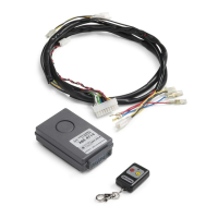
– Insert the crankshaft in the friction bearing.
NOTE:
– The crankshaft end with the thread for the primary pinion bolt
connection must point down.
– The conrod for the rear cylinder
1 must face up. Both conrods
should be in the position shown in the illustration.
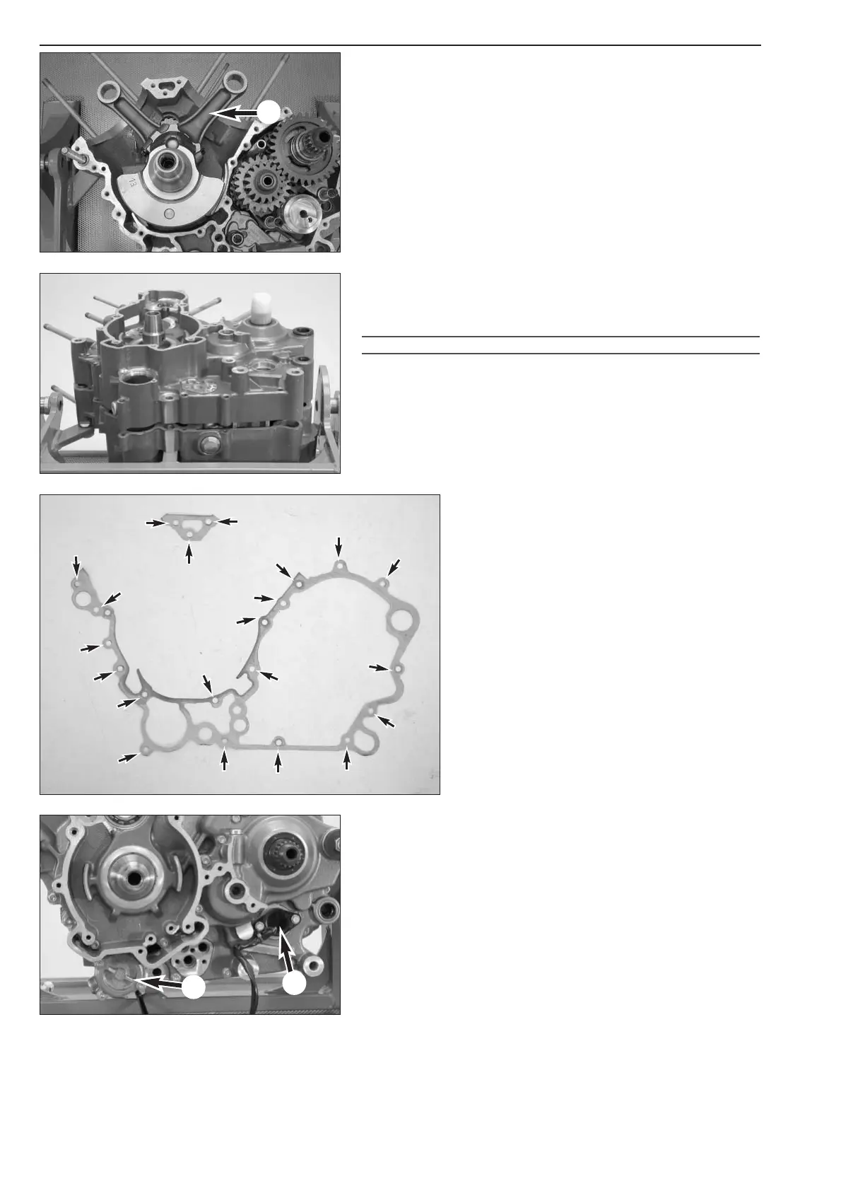
– Mount the case dowel pins and put a new case gasket in place.
NOTE: additional housing dowels are used for items 19 and 21 (see
photo below) starting with the 2005 model.
Case half
– Slide the protective sleeve 600.29.005.000 over the countershaft.
– Slip on the generator-end case half. Tap lightly on the countershaft
with a rubber hammer if necessary.
!
CAUTION
!
D
O NOT TRY TO DRAW THE TWO CASE HALVES TOGETHER WITH THE CASE BOLTS.
– Screw in all HH case bolts (see illustration for bolt
lengths) and tighten to 10 Nm.
NOTE:
– the bolts should be tightened in the order shown
in the illustration (numbers in parentheses).
– Screws item 19 and 20 were changed from
M6x65 to M6x75 and screw item 21 to M6x70
starting with model year 2005.
– Move the case into a horizontal position with the
generator side facing up.

 Loading...