6-7
3
4
5
6
7
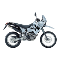
– Screw on the generator-end timing chain tensioning rail 1. Apply
Loctite 243 to the bolt and tighten to 20 Nm.
!
CAUTION
!
M
AKE SURE NO LOCTITE THREAD ADHESIVE IS ON THE PIVOT AREA OF THE BOLT
.
THIS COULD CAUSE THE TIMING CHAIN TENSIONING RAIL TO BLOCK AND BREAK.
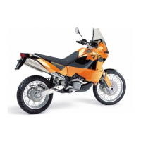
Balancer shaft
– Heat the generator-end bearing of the balancer shaft evenly with a
heat gun (up to model 2004).
NOTE: a roller bearing without an inner ring is used instead of the ball
bearing starting with the 2005 model; these bearings no longer need to
be warmed.
– Fit the timing chain on the generator end (pay attention to the
running direction if the chain has already been used) and slide into
the balancer shaft
2. The timing chain must be placed over the rear
sprocket.
– Check the balancer shaft for smooth operation.
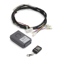
Freewheel
– Slip the freewheel 3 on the crankshaft and attach the locking
device
4 with 2 M6x16 bolts. Apply Loctite 243 to the bolts and
tighten to 10 Nm.
– Attach the lower starter idler gear
5 to the balancer shaft with the
collar on the inside.
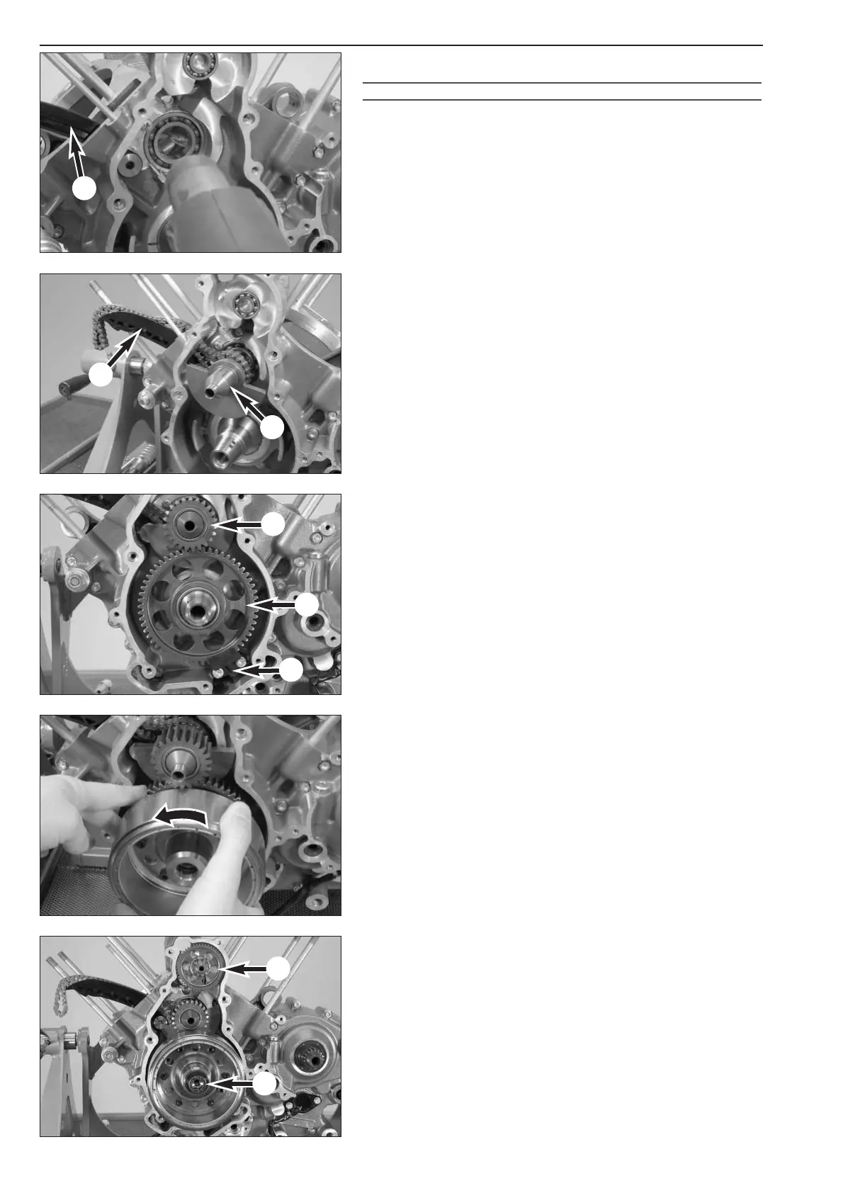
Rotor
– Hold the freewheel with your finger while mounting the rotor, turning
it in a counterclockwise direction.
– Mount the rotor bolt
6 with disk, apply Loctite 243 to the bolt and
tighten to 180 Nm (M16) or 150 Nm (M16x1.5).
NOTE:
– to prevent the crankshaft from turning, block it with the engine lock
bolt.
– Check the force fit of the rotor on engines that do not have a
woodruff key fixture - see Technical Information, Chapter 1.
– Mount the upper starter idler gear
7 on the journal.
1
2
1

 Loading...