6-9
1
2
3
4
5
6
7
8
9
bk
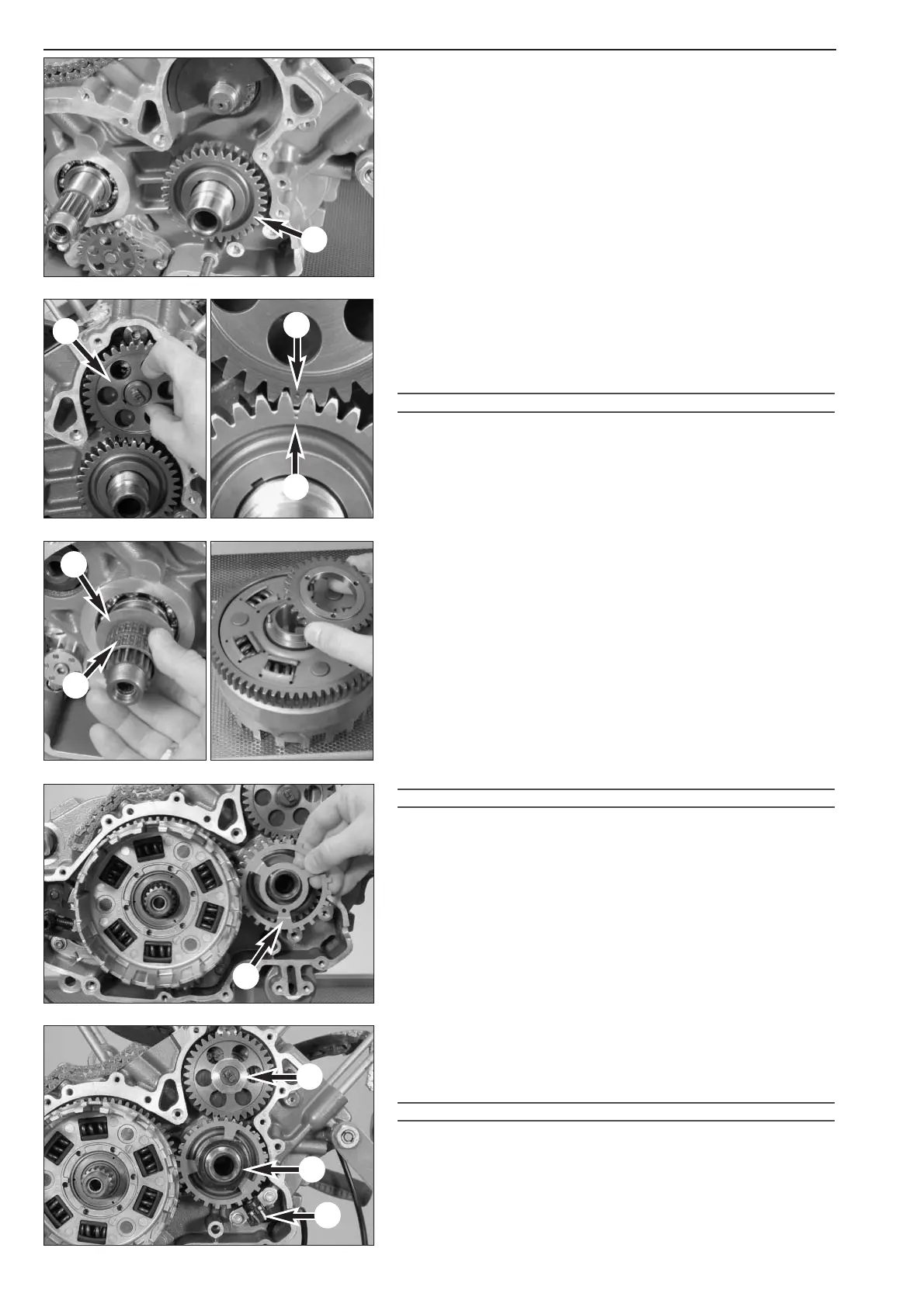
Primary pinion
– Mount the woodruff key for the primary pinion in the shaft groove (if
dismounted).
– Mount the primary pinion
1 with the longer collar towards the rear.
The bore for the pickup ring must face towards the outside.
– Mount the gear wheel of the balancer shaft
2 with the collar facing
the back (up to the 2004 model).
– From the 2005 model: slide on the preassembled spreader drive,
making sure the drive wheel and tensioning wheel do not fall apart;
pull out the pin.
!
CAUTION
!
T
URN THE BALANCER SHAFT UNTIL THE MARKS ON GEARS FOR THE CRANKSHAFT
3 AND BALANCER SHAFT 4 COINCIDE AS SHOWN IN THE ILLUSTRATION. MAKE
SURE THE TIMING CHAINS DO NOT GET CAUGHT
.
NOTE: when the marks coincide the first cylinder of the engine is in
the TDC position.
– Slide a 30.3 x 50 x 2 mm spacer washer
5 and a needle bearing 6
on the clutch shaft.
– Mount the gear for the oil pump drive on the back of the outer
clutch hub. The gear is secured by 3 needle rollers.
Outer clutch hub
– When slipping the outer clutch hub onto the shaft, leave enough
room for the pickup ring
7 which is held in place by a pin.
!
CAUTION
!
–
T
HE PIN ON THE PICKUP RING MUST ENGAGE IN THE HOLE OF THE PRIMARY PINION
.
–T
HE PICKUP RING IN
CARBURATOR AND INJECTION MODELS ARE
DIFFERENTIATED BY THE POSITION OF THE
"TOOTH GAP"; THEY CANNOT BE
INTERCHANGED
.
– After mounting the ring gear on the crankshaft, push the outer
clutch hub up to the stop, moving the oil pump wheel back and
forth to make the procedure easier.
– Mount a 33.2 x 46 x 2 disk and nut
8 (46 mm) on the primary
pinion (LH thread). Apply Loctite 243 to the nut and tighten to
130 Nm.
– Mount a 20.2 x 33 x 1.5 mm disk and nut
9 on the balancer shaft.
Apply Loctite 243 to the nut and tighten to 150 Nm (up to the
2004 model).
– Mount the washer 20.2x34x1 mm and the spring washer
30.5x46.5x0.6-1.5, apply Loctite 243 to the nut 9 (A/F 30 mm) on
the balancer shaft and mount, tighten the nut to 120 Nm (from the
2005 model).
!
CAUTION
!
T
HE GEAR WHEEL AND BALANCER SHAFT ARE PRESTRESSED STARTING WITH THE
2005 MODEL; THE NUT ON THE BALANCER SHAFT MAY ONLY BE TIGHTENED TO
120 NM OTHERWISE THE SPREADER DRIVE WILL BE DAMAGED.
– Screw on the pickup
bk. Apply Loctite 243 to the bolts (M6x16) and
tighten to 10 Nm. Press the cable duct into the recess in the case.
NOTE: the gap between the pickup and the pickup ring must be between
0.6 and 1.0 mm (950) or between 0.4 and 0.6 mm (990).

 Loading...