HYDRAULIC SYSTEM
L3560, L4060, L4760, L5060, L5460, L6060, WSM
8-M16
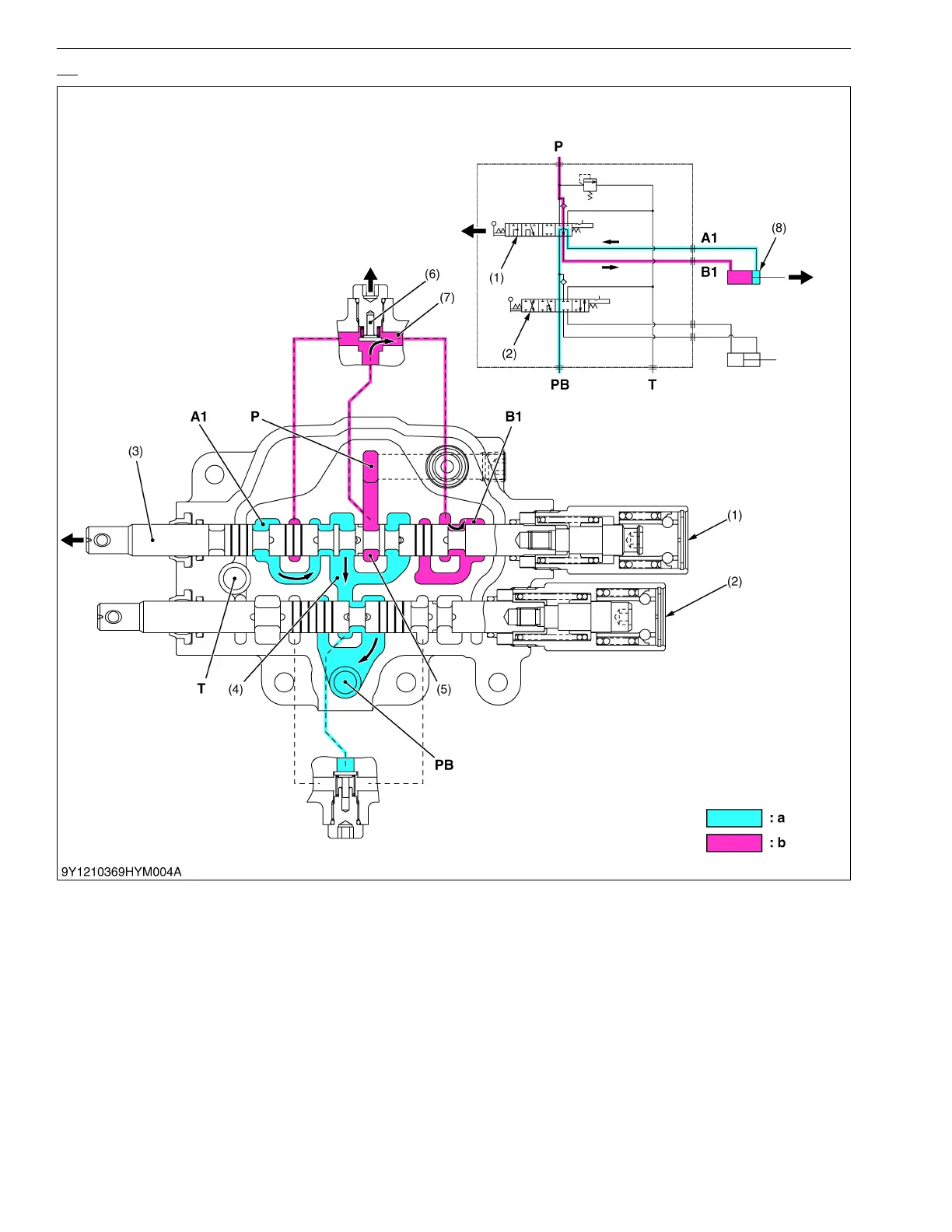
Up
1. When the hydraulic control lever is set to the "UP" position, the spool (3) of the boom control section (1) moves
to the left, which forms oil passages between passage 1 (7) and B1 port, and between A1 port and PB passage
1 (4).
2. As the oil passage from the neutral passage 1 (5) to the PB passage 1 (4) is closed by the spool (3), the
pressure-fed oil from the P port opens the load check valve (6) and flows through the notched section of the spool
(3) and B1 port to extend the boom cylinder (8).
3. Return oil from the boom cylinder (8) flows from the A1 port through the passage in the spool (3) and PB passage
1 (4) to the bucket control section (2).
9Y1210824HYM0019US0
(1) Boom Control Section
(2) Bucket Control Section
(3) Spool
(4) PB Passage 1
(5) Neutral Passage 1
(6) Load Check Valve
(7) Passage 1
(8) Boom Cylinder
P: Pump Port
T: Tank Port
A1: A1 Port
(From Boom Cylinder)
B1: B1 Port
(To Boom Cylinder)
PB: Power Beyond Port
a: Low Pressure
b: High Pressure
 Loading...


