ELECTRICAL SYSTEM
L3560, L4060, L4760, L5060, L5460, L6060, WSM
9-S49
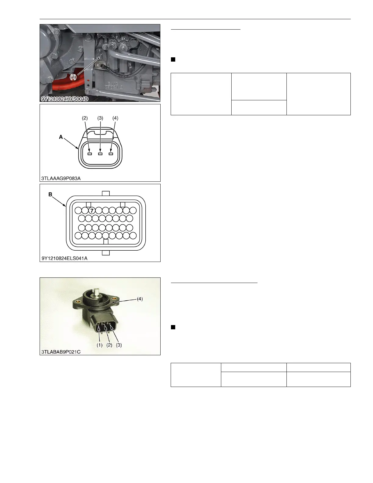
Traveling Speed Sensor
1. Measure the resistance between terminal 7 of main ECU
connector B and terminal 2 of sensor connector.
2. If 0 ohm is not indicated, the wiring harness is faulty.
• It is not necessary to adjust any kind of mode.
9Y1210824ELS0042US0
(7) Checking Sensor and Switch for GST
GST Lever Sensor Resistance
1. Measure the resistance between terminal a (1) and c (3).
2. Then, check resistance between terminal a (1) and b (2) while
slowly turning the sensor shaft.
3. It is OK if the resistance value approximates to the value shown
in the table below.
• When replacing the sensor, be sure to adjust the mode "E".
(Reference)
• The change of resistance can be checking easily when an
analog tester is employed.
9Y1210824ELS0043US0
Resistance
Terminal 2 of sensor
connector – Terminal 7
of main ECU
connector B
0 Ω
Terminal 3 of sensor
connector – Chassis
(1) Traveling Speed Sensor
(2) Terminal 1
(3) Terminal 2
(4) Terminal 3
A : Connector of Wire Harness Side
B : Main ECU Connector B (34P) of
Wire Harness Side
Resistance
Terminal a – Terminal c 1.6 to 2.4 kΩ
Terminal a – Terminal b
Resistance is normal if
smoothly changing
(1) Terminal a
(2) Terminal b
(3) Terminal c
(4) GST Lever Sensor
 Loading...


