HYDRAULIC SYSTEM
L3560, L4060, L4760, L5060, L5460, L6060, WSM
8-S22
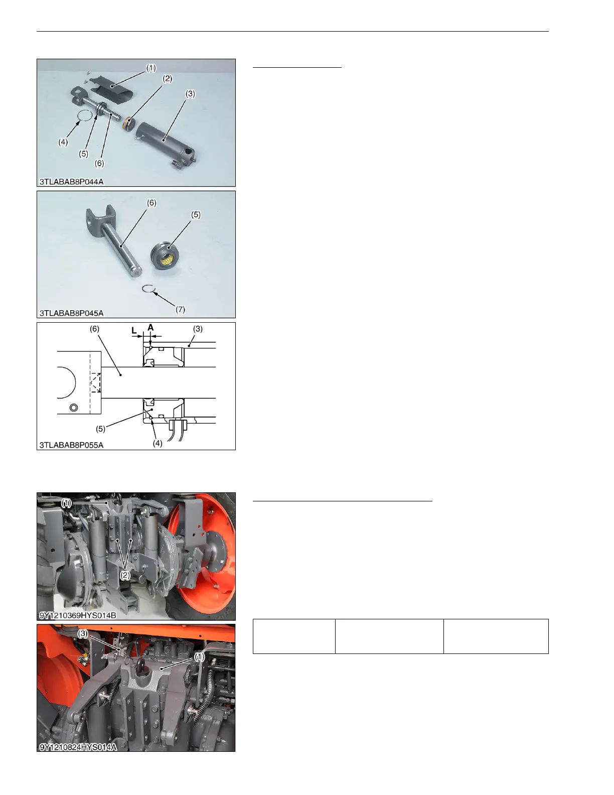
(2) Disassembling Hydraulic Cylinder
Hydraulic Cylinder
1. Remove the cylinder cover (1).
2. Remove the liquid gasket from top of head (5).
3. Slightly tap-in the head (5) to inside, and remove the internal
snap ring (4) by using the small screwdriver.
4. If the internal snap ring (4) cannot be removed by
above-mentioned method, remove it by the following procedure.
• Carefully clamp the cylinder tube (3) in a vise.
• Drill approx. 2.5 mm (0.1 in.) diameter hole on the cylinder
tube (position "A") just over the internal snap ring (4) as
shown in figure.
• Use a small screwdriver and remove the internal snap ring
(4). Simultaneously support this action by pushing from the
outside of the cylinder tube with another small screwdriver
or similar tool.
5. Draw out the rod (6) and head (5).
6. Inject the compressed air through the oil inlet port of the cylinder
tube (3), and remove the piston (2).
7. Remove the external snap ring (7), and remove the head (5).
(When reassembling)
• Apply transmission fluid to the piston (2), head (5) and cylinder
tube (3).
• Be careful not to damage the O-ring, backup ring and seal.
• Apply liquid gasket (Three Bond 1208C or equivalent) to the top
of head (5), while pressing the head (5) against internal snap
ring (4).
• After reassembling the cylinder, be sure to close the drilled hole
by liquid gasket.
9Y1210824HYS0028US0
(3) Separating Lift Arm Support
Top Link Holder and Lift Arm Support
1. Disconnect the position control feedback rod (3).
2. Remove the top link holder (2).
3. Remove the lift arm support (1).
(When reassembling)
• Apply liquid gasket (Three Bond 1208C or equivalent) to joint
face of the lift arm support and transmission case after eliminate
the water, oil and stuck liquid gasket.
• After reassembling, be sure to adjust the position control
feedback rod length. (See page 8-S13.)
9Y1210824HYS0029US0
(1) Cylinder Cover
(2) Piston
(3) Cylinder Tube
(4) Internal Snap Ring
(5) Head
(6) Rod
(7) External Snap Ring
A: Position for drilling
L: 6.0 mm (0.24 in.)
Tightening torque
Top link holder mounting
screw
78 to 90 N·m
7.9 to 9.2 kgf·m
58 to 66 lbf·ft
(1) Lift Arm Support
(2) Top Link Holder
(3) Position Control Feedback Rod
 Loading...


