ELECTRICAL SYSTEM
L3560, L4060, L4760, L5060, L5460, L6060, WSM
9-S47
9Y1210824ELS0039US0
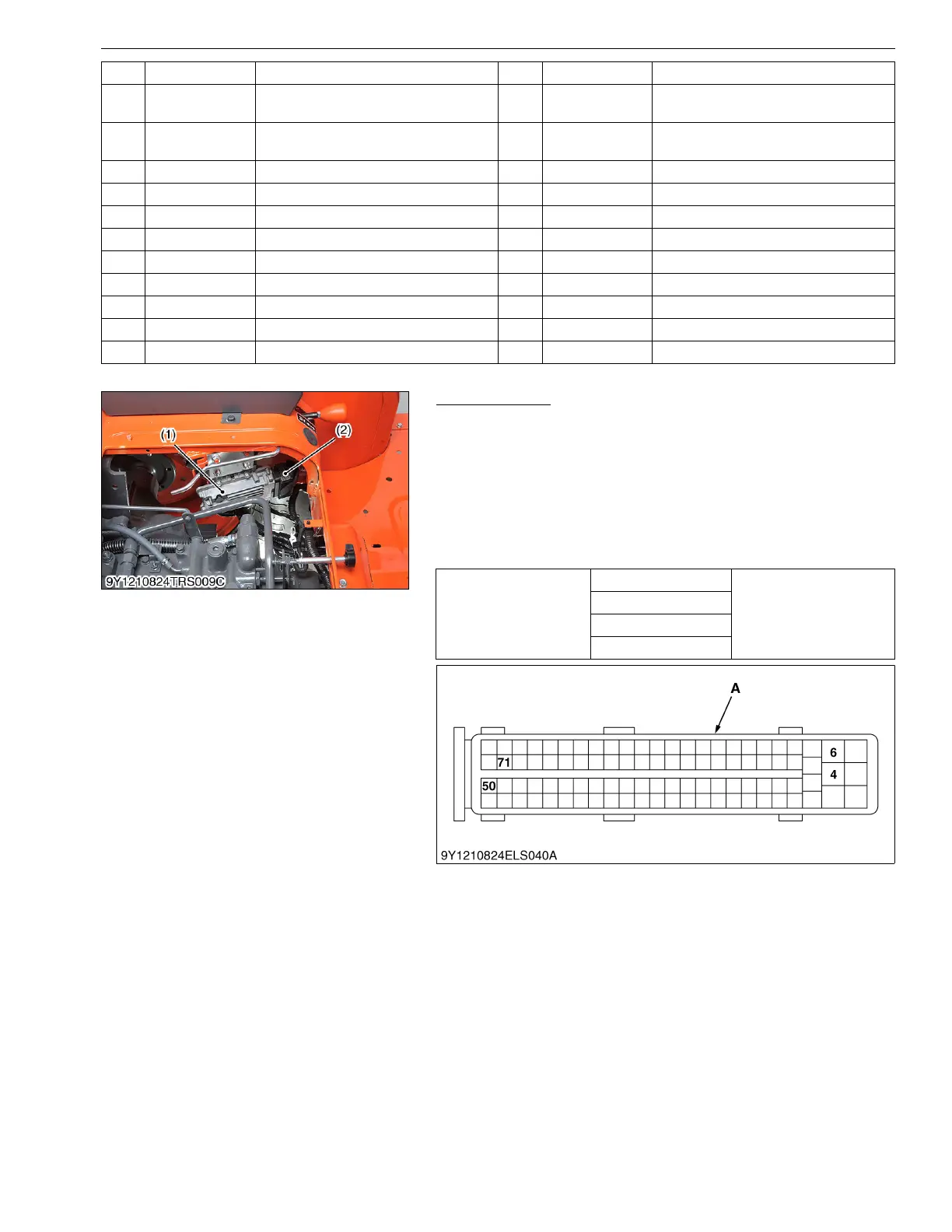
Battery Voltage
1. Disconnect the connector (2).
2. Measure the voltage between terminal 50 (+) and chassis.
3. Turn the main switch ON.
Measure the voltage between terminal 4 (+) and chassis.
4. Measure the voltage between terminal 6 (+) and chassis.
5. Measure the voltage between terminal 71 (+) and chassis.
6. If the measurement is not approximately battery voltage, check
the relating electric circuit.
9Y1210824ELS0040US0
37 B
Intake Throttle Valve Position Sensor
(Signal)
84 R Intake Throttle Valve Motor (DC Motor +)
38 B
DPF Differential Pressure Sensor
(Signal)
85 R Intake Throttle Valve Motor (DC Motor −)
39 R Crankshaft Position Sensor (+) 86 Y Intake Air Temperature Sensor (Signal)
40 ––87 ––
41 ––88 ––
42 ––89 YSCV (−)
43 ––90 ––
44 B Camshaft Position Sensor (−) 91 ––
45 R Camshaft Position Sensor (+) 92 ––
46 W Camshaft Position Sensor (Signal) 93 ––
47 ––94 ––
No. Color of wiring Terminal Name No. Color of wiring Terminal Name
Voltage
Terminal 50 – Chassis
Approx. battery voltage
Terminal 4 – Chassis
Terminal 6 – Chassis
Terminal 71 – Chassis
(1) Engine ECU
(2) Connector
A : Connector of Wire Harness Side
 Loading...


