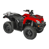
7. Slide the
hub
out
of
th
e knuckle and
set
aside.
8.
Remove the cap
sc
r
ews
and lock nuts securing the
knu
ck
le to
th
e A-arms. Disc
ard
the
lock outs.
•NOTE:
Never reuse a
Jock
nut. Once a lock nut
has been removed, it must be replaced with a new
lock nut.
9.
Remove the cap
sc
r
ews
and lock nuts
sec
uring the
A-arms to the
frame; then remove
the
A-a
nn
s.
•NOTE:
If
removing the upper right A-arm, it will
be
necessary
to
disconnect the brake hose from
the A-arm.
CLEANING
AND
INSPECTING
•NOTE:
Whenever a part is worn excessively,
cracked,
or
damaged in any
way,
replacement is
necessary.
I. Clean
alJ
A-arm components usmg a pressure
was
her.
2. Inspect the A-arm for b
en
ds. cracks, and
wom
bushings.
3.
ll1Sp
ect
the frame mounts for signs
of
damage,
wea.J;
or weldment damage.
INSTALLING
I. Install the A-ann assemblies into
the
frame
mounts and secure with the cap screws and new
l
ock
nuts. Only finger-tighten at this time.
2. Slide the knuckle onto the drive
a.;x
le
and
into posi-
tion on the A-arms: then secure the knuckle
to
the
A-arms with cap screws and
new
lock nuts.
Tighten
to
35 ft-lb.
3. Tighten the hardware
sec
uring the A-
a.n
ns to the
fran1e
mounts (from step
l)
to
35 ft-lb.
4. Apply grease
on
the drive axle splines: then install
the hub assembly onto
th
e drive axle.
5. Secure the bub assembly with
the
out. Tighten
o
nl
y until snug.
6. Sec
ur
e
th
e brake
ca
]jper to the knuckle with the
two cap screws (right side only). Tig
ht
en the cali-
per
to
20 ft-lb.
7. Compress the hand brake lever and engage
th
e
brake l
ever
lock: then secure
the
hub nut (from
step 5) to the drive
a'X
le. Tighten to
200ft-lb
.
8. Install a n
ew
cotter pin
and
spread the pin
to
secure the nut.
9. Secure the shock absorber to the frame
,;o,rith
a cap
screw and new lock
nut. Tight
en
to
35
ft-lb.
10
.
Sec
ur
e the shock absorber to the
low
er A-arm with
a cap screw
and
new
lock
nut. Tighten to 20
ft
-lb.
II
. Sec
ur
e the boot guard
to
tbe l
ower
A~am1
with tbe
two cap screws. Tighten securely.
12
. Install the wheel and tighten to
40
ft-.lb.
13. Remove
the
ATV from
the
support stand.
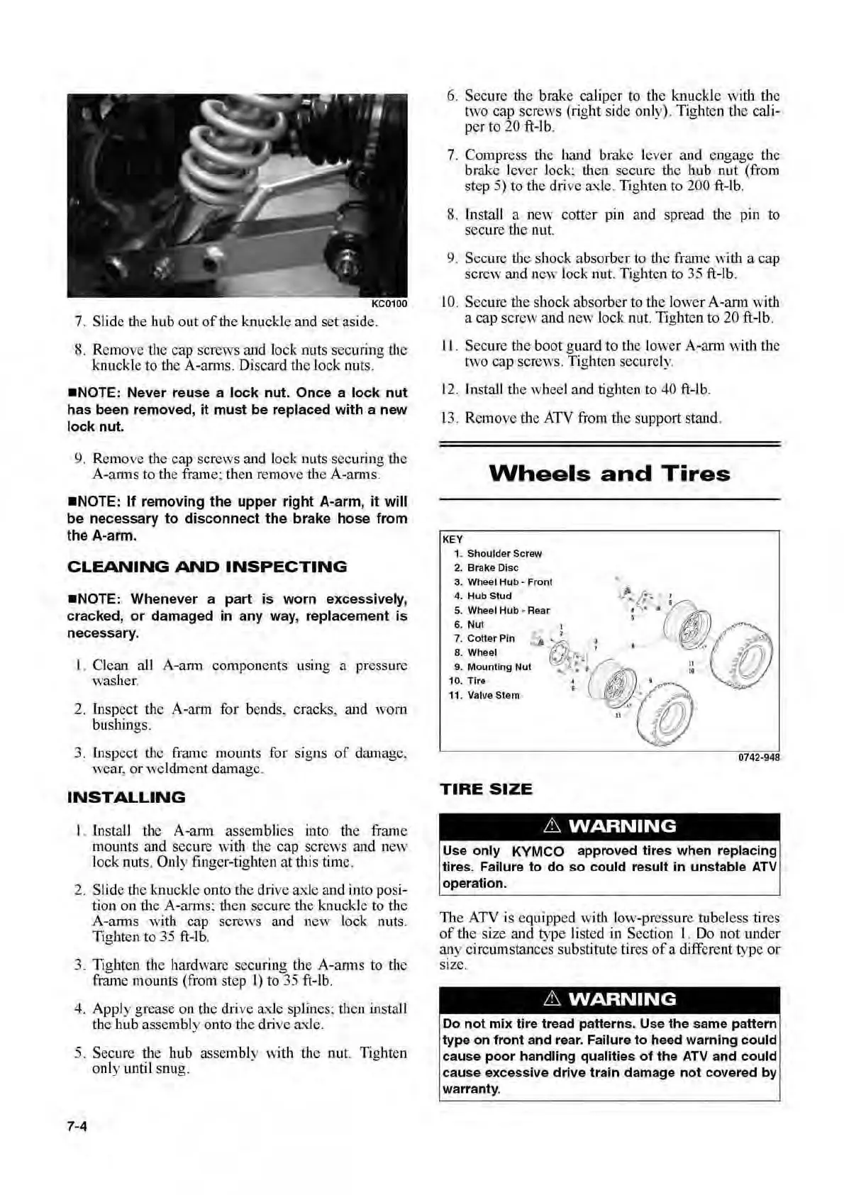
Wheels
and
Tires
KEY
1. Shoulder Screw
2. Brake
Disc
a.
Wheel
Hub
- Front
::
~::~~~b
"Rear
·
--
~
4•;
r~@
7.
CotterPin
1
· .,
l , (
-~
1
~
8. Wheel
~
~o~
fb!\
_
~
_·
-.~IJ
',,'
.~·
__
_
9.
M
ou
nting
Nut
_
~-
~
~
_
10
. T
ir
e 4 )
.,
, . I
11
. ValveStem
-r
<
..
ll
0742·948
TIRE
SIZE
6
WARNING
I
Use only KYMCO approved tires when replacing
tires.
Failure
to
do so could result in unstable
ATV
operation.
Th
e ATV is equipped with low-pressure tubeless tires
of
the size
and
type I isted in Section 1. Do n
ot
w.1der
a~y
c
ir
cumstances
subst
itute tires
of
a different type
or
SIZe.
6
WARNING
Do
not
mi
x tire tread patterns. U
se
the same patte
rn
type
on
front
and
rear. Failure
to
heed warning could
cause poor handling
qualities of the
ATV
and
could
cause excessive drive
tr
ain damage not covered
by
warran
ty
.
 Loading...