Speed
Sensor
1. Set the meter selector
to
the DC Voltage positi
on
.
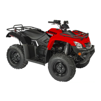
2. With appropr
iate
needle adapters
on
the meter
leads, connect the red tester
lead
to
the
vo
ltage lead
(V);
then
connect the black tester l
ead
to
the
gr
ound
lead
(G)
.
3.
Tum
the ignition switch
to
t11e
ON
positi
on
.
4.
The meter must show 12.0 volts.
5. Leave the black tester lead connected; then
con
-
nect
th
e
red
tester lead
to
the signal lead pin (S).
6.
Slowly move
the
ATV
forward
or
backward; the
meter must
show
0
and
6 volts alternately.
• NOTE:
If
the
s
en
s
or
te
sts are
within
s
pe
c
ifica-
tions
,
the
speedometer
must
be
replaced (s
ee
Sec-
tion
9).
To
replace a speed sensor, use the
fo
ll
ow
ing procedure.
1. Disconnect
t11e
three-wire connector
fi·om
the speed
sensor; then remove the cap screw securing the
sensor
to
the
sensor hous
in
g.
2.
Remove the sensor fr
om
the sensor housing
acc
ou
n
tin
g
for
an
0-r
ing.
5-6
3.
Install
tl1e
new speed sensor
into
the
housing with
new 0
-ri
ng lightly coated with multi-purpose
grease; then secure
t11e
sensor with
the
c.ap
screw (threads coated with bl
ue
Loctite
#
24~~).
Tighten securely.
C01)71
Ignition
Switch
The ignition
sw
itch hamess connects
to
the
sw
itch
witll
a three-pin connector.
To
access the connector,
remove the access panel
in
front of tlle handlebar.
VOLTA
G E
•NOTE
: Perform
thi
s
test
on
the
main
harne
ss
connector
.
1. Set the meter selector
to
the DC Voltage position ..
then
connect
t11e
black meter lead
to
ground.
3.
Meter must show battery voltage.
• NOTE:
If
the
meter
s
how
s
no
ba
ttery
voltaue,
trouble
s
hoot
the
battery
or
the
main
w
iring
har-
ness.
 Loading...