A. When using an
auto
m
at
ic batt
ery
C·harger,
al
ways
fo
ll
ow
the charger
man
u
factu
rer s
in
str
uctions.
B. Wh
en
using a constant-cur
rent
battery
charge
r,
u
se
t
he
fo
ll
owing
B
attery
Ch
arg
ing
Chart
.
..&.
CAUTION
Never exceed the standard charging rate.
A
WARNING
An overheated battery could explode causing severe
injury
or
death. Always
monitor
charging times and
charge rates
carefully. Stop charging
if
the
battery
becomes very warm
to
the
touch
. Allow
it
to
cool
before resuming charging.
Battery
Ch
arging
Chart
(Constant-Current
Charger)
Battery Voltage Charge Ch
ar
ge Time Req
uir
ed
(DC)
State
(at
1.5-2.0
Amps)
12.5
or
more 100% None
12.2-12.4
75
%-99% 3-6 hours
12.0-12.2 50%-74%
5-11
hours
11
.0-11.9 25%-49% 13 hours (minimum)
11
,5
or
less 0-24% 20 hours (minimum)
•NOTE
:
If
the
battery voltage
is
11.5 DC Volts
or
less
,
some
chargers
may
''
cut
off
" and fail
to
charge.
Itt
this
occur
s,
connect
a
fully
char
ged
booster battery
in
parallel
(positive
to
positive
and
negati
ve
to
negative)
for
a
short
period
of
time
with
the
charger connected. After 10-15 minutes,
di
s
con-
nect
the
booster
battery leaving
the
charger
con-
nected
and
the
charger
should
continue
to
charge.
If
the
charger "
cuts
off
;'
replace the battery.
8. After charging
th
e battery for the
spec
ified
time
.
remov
e the battery
charger
and all
ow
the battery
to
si
t for 1-2 ho
ur
s.
9.
Connect
the multim
eter
and
test
the
battery
vo
lt-
age
.
The
me
ter
sh
ould
r
ead
1
2.5
or m
ore
DC
Vo
lts.
l
ft
he voltage is
as
specified. the battery is ready
fo
r service.
•NOTE
:
If
voltage
in
step
9
is
below
specification
s,
charge
the
battery
an
additional
1-5
hours
;
then
retest.
10. Place the battery in the b
attery
co
mpartment:
then
coat
the
battery posts
an
d
ca
ble
ends
with a light
coat
ofmul
ti-
pu.rpose
grease.
&
CAUTION
Before installing the battery, make sure the ignition
switch
is
in
the OFF position.
2-4
II .
Connect
the
battery
cab
l
es
(positive
cable
first):
then install the
ba
tt
ery
bo
ld-
do\.
vn.
A
CAUTION
~
Connecting cables
in
reverse (positive
to
negative
and negative
to
positive) can cause serious damage
to
the
elec
trical
system .
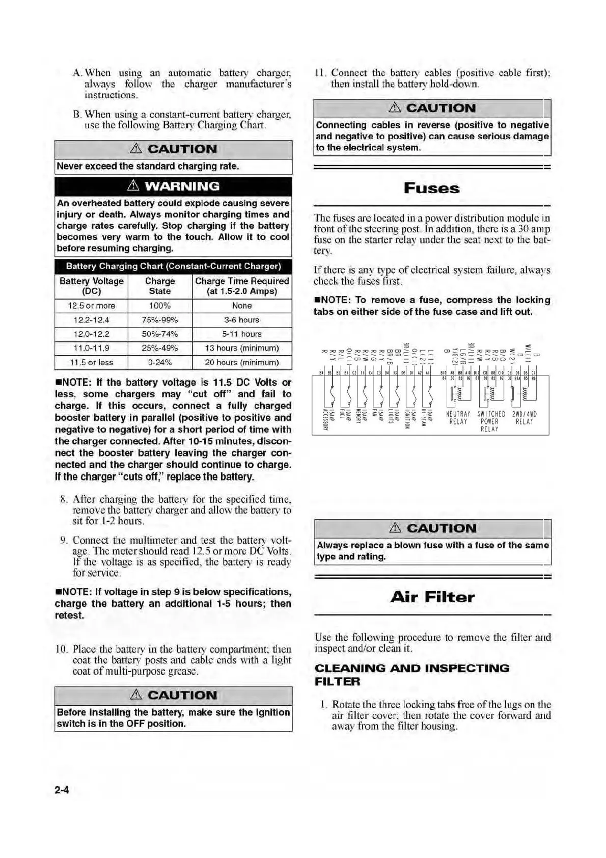
Fuses
The
fuses
are
located
in
a
powe
r distribution mod
ul
e in
front
of
the
stee
ring post. In
addition
, there is a
30
amp
fi
t
se
on
the starter relay 1
mder
the
seat
next
to
the
bat-
tery.
If t
he
re is
any
type
of
electricaJ system
failu.re
, al
ways
check the
fuses
first.
•NOTE:
To remove a fuse,
compress
the
locking
tabs
on
either
side
of
the
fuse
case
and
lift
out.
"'"
=
;;o::;o;;oO::o;;o::o;;z:J
OJCD;=:.Or-r-
--.-.--.-.-.:::o~-...,--
-<
~
=Cil.:::eC')-<-
-=N-
-
~
-
--
11
81
82
Bl U
(I
<• 0
tl
OJ
OJ
t l A1 &I
NEUTRAY
S
WI
TC
H
ED
2WDI4W
D
RELAY
POWER
RE
L
AY
RE
L
AY
&
CAUTION
~
Always replace a blown
fuse
with a fuse
of
the
sarne
type and rating.
Air
Filter
Use the
following
procedure
to
r
emove
the
filter
and
inspect
and/or
cl
ean
it.
CLEANING
AND
INSPECTING
FILTER
1.
Rotate the
th
r
ee
locking
ta
bs
free
of
the
lu
gs
on
th
e
air
filter cover:
th
en
rotate
the
cover
fo
r
war
d and
away
from
the filter housing.
 Loading...