Brakelight
S\Nitch
(Pressure)
The brakelight switch
is
located on the top Clfthe
am>-
i
li
ary
br
ake
master
cylinder
and
is
pr
essure
activa
ted
by
U1e
hand brake
or
th
e auxiliary brake p
te
dal. Titis
switch also activates
tl1c
sta
rt-in-gear (S
IG
) re
la
y in
the power distribution module (PDM).
•NOTE
: The
ignition
switch
must
be
in
the
ON
position.
VOLTAGE
(Wiring
Harness
Side)
I.
Set
the meter
se
l
ec
tor
to
the DC
Vol
tage posi
ti
on.
2.
Conn
ec
t
th
e red t
es
ter to the brown/black wire;
then co1mcct the black tester lead to grou
111d
.
3. The me
ter
must sh
o'rv
battery voltage.
•NOTE
:
If
the
meter
shows
no
battery voltage,
troubleshoot the battery,
fu
se,
switc
h,
or
the
main
wiring harness.
•NOTE
:
If
the meter
shows
battery
voltage
,
the
main
wi
ring
harness
is
good; proceed
to
test
th
e
switch/co
mpon
e
nt
or
connector
.
RESISTANCE
(Switch)
&
CAUTION
11
Always disconnect the battery when porformlng
resistance tests
to
avoid damaging the mul·timeter.
l.
Remove
the
spad
e
con
nectors from
U1
e brake
switch.
2.
Set
the
meter
se
lector
to
the OHMS position.
3.
Co
m1
e
ct
the red tester lead to one switch tcnninal:
tbeu conn
ect
U1e
black tester lead to
U1e
ot
h
er
switch
te
nn
inal.
4. When the
brake pedal is
depr
e
ss
ed.
the
meter mu
st
sho"
less than I ohm.
•NOTE
:
If
the meter s
how
s more
than
1
ohm
of
resistance, r
ep
lace
the
switc
h.
THERMOSTATIC
SWITCH
I.
Con
nect the rueter ]
ca
ds (selector
i11
th
e OHMS
position) to the switcb contacts.
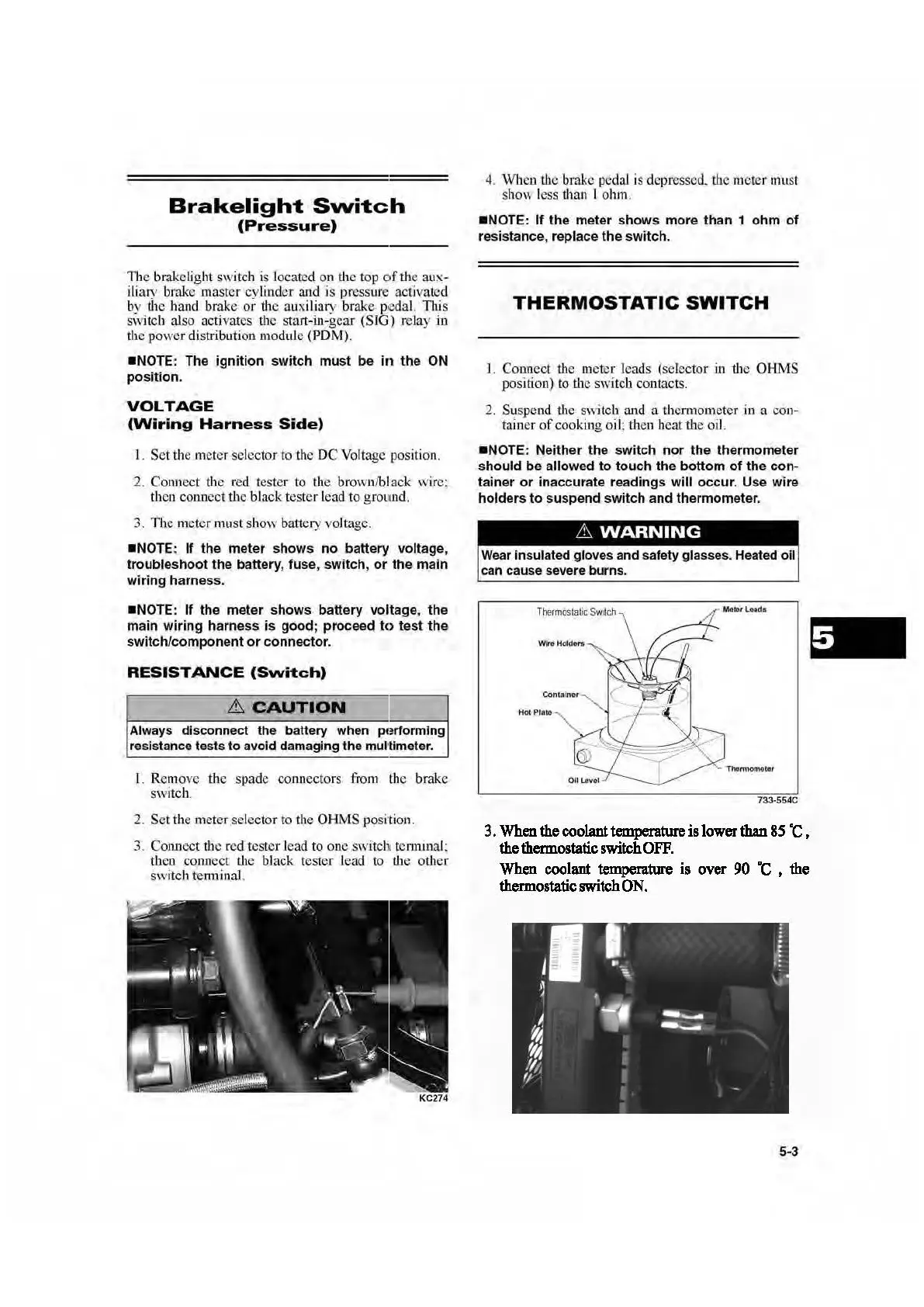
2. Suspend the switch and a thcmwmeter
in
a con-
tain
er of cooking
oi
l:
then
heat the
oi
l.
•NOTE
: Neither the
switch
nor
the
thermometer
should
be
allowed
to
touch
the
bottom
of
the
con-
tainer
or
inaccurate readings
will
occur
. Use
wire
holders
to
suspend
sw
itch
and
thermometer.
Wear
insulated gloves and safety glasses. Heated oil
can
cause severe burns.
Th
e
r
most~tic
Sw
itch
HotPlate
733·
554C
3.
When
the coolant temperature is lower than 85
"C,
the thermostatic switch
OFF.
When
coolant temperature is over 90
·c
, the
thermostatic switch
ON.
5-3
 Loading...