Steering/Frame
•NOTE: Cri
ti
cal torque specifica
tion
s
a11e
located
in
Section 1.
Steering
Post/Tie
R:
ods
REMOVING
l.
Remove the front
bod
y panel/fender (see Front
Body
Panel/Fender
in
this section).
2.
Remo
ve
the steering post cover; then r
emove
the
cap screws securing the handlebar
ca
ps and move
the handle
bar
out
of
the wav. Account
fi:>r
the two
handlebar caps. ·
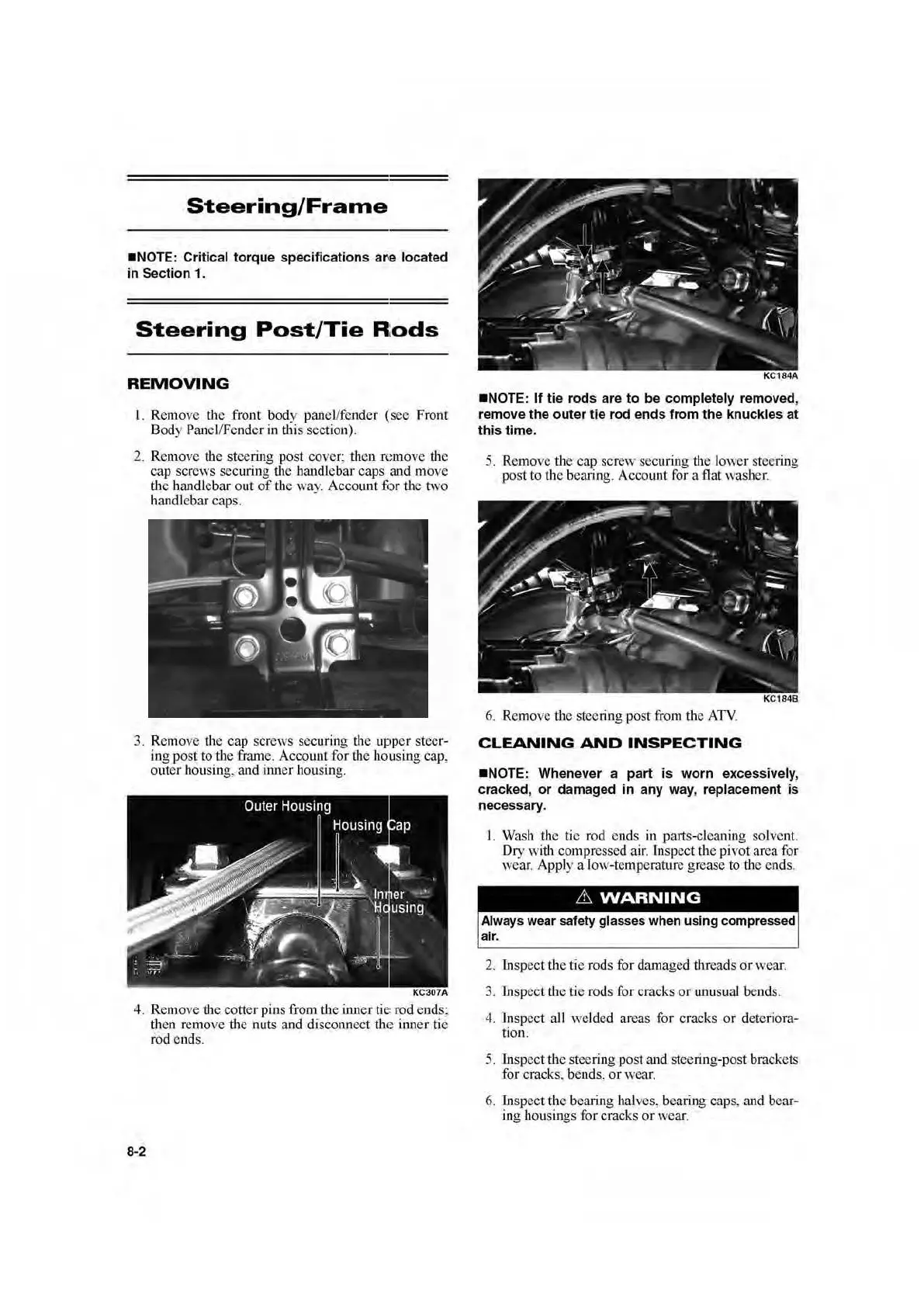
3. Remove the cap screws securing the upp
er
steer-
ing
po
st
to
the frame. Account for the
hou
sing cap,
outer housing.
and inner housing.
KC307A
4. Remove the cotter pins from the inn
er
ti
e:
rod e
nd
s:
then remove
the
nuts and disconnect
th1
~
inner tie
rod c
ud
s.
8-2
•NOTE:
If
tie
rods are
to
be completely removed,
remove
the
outer
tie rod ends from
the
knuckles
at
this
time
.
5. Remo
ve
th
e cap scr
ew
sec
uring the l
ower
st
eer
in
g
post to the bearing.
Ac
cm
mt for a flat washer.
KC184B
6.
Remove the steering post from the
ATV
.
CLEANING
AND
INSPECTING
•NOTE
: Whenever a
part
is w
orn
ex
ce
ss
ively,
c
rack
ed,
or
damaged
in
any w
ay
, replacement is
necessary.
I.
Wash the tic rod e
nd
s in pruts-cleaning solvent.
D
ry
with compressed
air
. inspect the pivot area for
wear. Apply a l
ow-
temperature grease to
th
e ends.
Always wear safety glasses when using compressed
a
ir
.
2. Inspect
the
tie rods for damaged threads or wear.
3. insp
ec
t the tie rods for cracks
or
un
usual bends.
4.
Jn
spcct all
we
lded areas for cracks
or
deteriora-
tion.
5. Inspect the steering post and steering-post brackets
for cracks. bends,
or
wear.
6.
In
sp
ect
the bearing halves, bearing caps. and bear-
ing hou
si
n
gs
for cracks
or
wear.
 Loading...